Gr-limesdr Plugin for GNURadio: Difference between revisions
| Line 238: | Line 238: | ||
: Index (CH0/CH1) shows which channel is configured (see Chip mode setting and CH0 setting). | : Index (CH0/CH1) shows which channel is configured (see Chip mode setting and CH0 setting). | ||
* '''Gain''': Controls combined RX gain settings. | * '''Gain''': Controls combined RX gain settings. | ||
** Gain range must be | ** Gain range must be 0dB–70dB. | ||
: Index (CH0/CH1) shows which channel is configured (see Chip mode setting and CH0 setting). | : Index (CH0/CH1) shows which channel is configured (see Chip mode setting and CH0 setting). | ||
Revision as of 12:17, 24 April 2018
Introduction
LimeSDR is a low cost, open source software defined radio (SDR) platform that can be used to support just about any type of wireless communication standard. This document provides an overview of the installation process and operation of the gr-limesdr plugin for GNU Radio software. Currently this plugin supports LimeSDR-USB and LimeSDR-Mini boards.
Installation
This section covers gr-limesdr plugin installation instructions. Currently plugin supports only Linux platform. Tutorial is based on Ubuntu operating system.
Installing LimeSuite
Visit this link for information on how to install LimeSuite.
Installing GNU Radio
Visit this link for information on how to install GNU Radio.
Installing dependencies
Enter the following command in terminal to install Boost and SWIG:
sudo apt-get install libboost-all-dev swig
Building gr-limesdr from source
Downloading gr-limesdr source
Download gr-limesdr plugin by typing:
git clone https://github.com/myriadrf/gr-limesdr
Building and installing gr-limesdr from source
Enter the following commands in terminal:
cd gr-limesdr/build
cmake ..
make
sudo make install
sudo ldconfig
Now you should reload GNU Radio blocks by restarting GNU Radio or by pressing Reload blocks button in top bar as seen in Figure 1. gr-limesdr blocks appear under LimeSuite category.

Device configuration
LimeSuite Sink (TX)
First you should pick LimeSuite Sink (TX) from LimeSuite category as shown in Figure 2.

LimeSuite Sink (TX) block appears in GNU Radio workspace as shown in Figure 3.
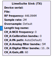
To configure block double click on it. Now you can see settings as shown in Figure 4.
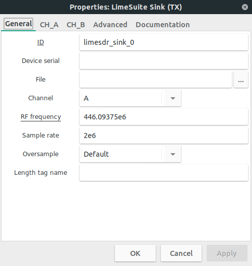
Available settings:
- ID: ID of current block in GNU Radio environment. This is usually left unchanged.
- Device number: Select which device to use from a list of devices to use multiple devices. This list can be obtained by running following command in your Linux terminal window:
LimeUtil --find
- Device type: To use available options for your device, select correct device type. Currently LimeSDR-Mini and LimeSDR-USB boards are supported.
- Chip mode: Use this setting to set single-input and single-output (SISO) or multiple-input and multiple-output (MIMO) chip mode. This setting enables/disables channels, sets correct number of streams and controls number of block inputs.
- In SISO mode you can select which channel to control (A or B) (see CH0 setting).
- In MIMO mode CH0 is always A channel and CH1 is always B channel.
- Note that not all boards (LimeSDR-Mini for instance) support MIMO mode.
- CH0: If SISO mode is selected (see Chip mode setting) set active channel (A or B) as CH0.
- Load settings: This setting lets you control the way settings are loaded to chip.
- If you want to load settings from .ini file (see File setting) generated by LimeSuiteGUI select YES.
- If you want to load settings from LimeSuite Sink (TX) block, select NO.
- Note that when loading from file there are a few settings left that are necessary to initialize streams (see Chip mode setting) or to control LimeSDR-Mini active power amplifier switch (see PA path setting). This setting should match in LimeSuite Sink (TX) and LimeSuite Source (RX) blocks for the same device.
- File: When Load settings (see Load settings setting) set to YES here you should select .ini file which you configured and saved by using LimeSuiteGUI. This setting should match in LimeSuite Sink (TX) and LimeSuite Source (RX) blocks for the same device.
- Center frequency: Set RF center frequency for TX (both channels).
- LimeSDR-USB supports RF center frequency in range 100kHz–3.8GHz.
- LimeSDR-Mini supports RF center frequency in range 10MHz–3.8GHz.
- Sample rate: Select sample rate for TX.
- LimeSDR-USB sample rate must be no more than 61.44 MS/s.
- LimeSDR-Mini sample rate must be no more than 30.72 MS/s.
- Note that LimeSDR-Mini supports only the same sample rate for TX and RX.
- Oversample: Oversample lets you sample TX signal at a higher rate than would be required to just preserve the desired signal frequencies.
- Possible values (multipliers): Default, 0, 1, 2, 4, 8, 16, 32.
- Default value uses highest possible value based on other settings. Oversample is connected to sample rate (see Sample rate setting) and there are limitations as show in Table 1 and Table 2. Note that LimeSDR-Mini supports only the same oversample for TX and RX.
| Sampling rate range (x) | Possible oversampling value |
|---|---|
| (15.36 < x ≤ 30.72) MS/s | 1, 2, 4 |
| (7.68 < x ≤ 15.36) MS/s | 1, 2, 4, 8 |
| (3.84 < x ≤ 7.86) MS/s | 1, 2, 4, 8, 16 |
| X ≤ 3.84 MS/s | 1, 2, 4, 8, 32 |
| Sampling rate range (x) | Possible oversampling value |
|---|---|
| (30.72 < x ≤ 61.44) MS/s | 1, 2, 4, 8 |
| (15.36 < x ≤ 30.72) MS/s | 1, 2, 4, 8, 16 |
| X ≤ 15.36 MS/s | 1, 2, 4, 8, 32 |
- Calibration: Turn TX DC offset and IQ imbalance calibration ON/OFF for each channel. Index (CH0/CH1) shows which channel is configured (see Chip mode setting and CH0 setting).
- Calibration bandw.: When calibration is turned ON (see Calibration setting) this setting is used to set bandwidth for TX calibration of each channel. This value should be equal to your signal bandwidth.
- Calibration bandwidth range must be 2.5MHz–120MHz.
- Index (CH0/CH1) shows which channel is configured (see Chip mode setting and CH0 setting).
- PA path: Select active power amplifier path of each channel.
- Possible selections: BAND1, BAND2.
- This setting also controls LimeSDR-Mini board path switch (BAND1/BAND2). Index (CH0/CH1) shows which channel is configured (see Chip mode setting and CH0 setting).
- Analog filter: Turn TX low-pass analog filter ON/OFF for each channel. Index (CH0/CH1) shows which channel is configured (see Chip mode setting and CH0 setting).
- Analog filter bandw.: If TX analog filter is turned ON (see Analog filter setting) enter analog filter bandwidth for each channel.
- TX analog filter bandwidth range must be 5MHz–130MHz.
- Index (CH0/CH1) shows which channel is configured (see Chip mode setting and CH0 setting).
- Digital filter: Turn TX digital filters (GFIR) ON/OFF for each channel. Index (CH0/CH1) shows which channel is configured (see Chip mode setting and CH0 setting).
- Digital filter bandw.: If TX digital filter is turned ON (see Digital filter setting) enter digital filter bandwidth for each channel.
- TX digital filter bandwidth should not be higher than sampling rate.
- Index (CH0/CH1) shows which channel is configured (see Chip mode setting and CH0 setting).
- Gain: Controls combined TX gain settings.
- Gain range must be 0dB–60dB.
- Index (CH0/CH1) shows which channel is configured (see Chip mode setting and CH0 setting).
LimeSuite Source (RX)
First you should pick LimeSuite Source (RX) from LimeSuite category as shown in Figure 5.

LimeSuite Source (RX) block appears in GNU Radio workspace as shown in Figure 6.
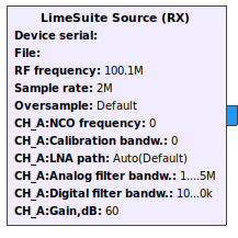
To configure block double click on it. Now you can see settings as shown in Figure 7.
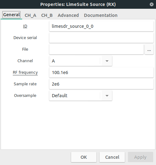
Available settings:
- ID: ID of current block in GNU Radio environment. This is usually left unchanged.
- Device number: Select which device to use from a list of devices to use multiple devices. This list can be obtained by running following command in your Linux terminal window:
LimeUtil --find
- Device type: To use available options for your device, select correct device type. Currently LimeSDR-Mini and LimeSDR-USB boards are supported.
- Chip mode: Use this setting to set single-input and single-output (SISO) or multiple-input and multiple-output (MIMO) chip mode. This setting enables/disables channels, sets correct number of streams and controls number of block outputs.
- In SISO mode you can select which channel to control (A or B) (see CH0 setting).
- In MIMO mode CH0 is always A channel and CH1 is always B channel.
- Note that not all boards support MIMO mode.
- CH0: If SISO mode is selected (see Chip mode setting) set active channel (A or B) as CH0.
- Load settings: This setting lets you control the way settings are loaded to chip.
- If you want to load settings from .ini file (see File setting) generated by LimeSuiteGUI select YES.
- If you want to load settings from LimeSuite Source (RX) block, select NO.
- Note that when loading from file there are a few settings shown that are necessary to initialize streams (see Chip mode setting) or to control LimeSDR-Mini active power amplifier switch (see PA path setting). This setting should match in LimeSuite Sink (TX) and LimeSuite Source (RX) blocks for the same device.
- File: When Load settings (see Load settings setting) set to YES here you should select .ini file which you configured and saved by using LimeSuiteGUI. This setting should match in LimeSuite Sink (TX) and LimeSuite Source (RX) blocks for the same device.
- Center frequency: Set RF center frequency for RX (both channels).
- LimeSDR-USB supports RF center frequency in range 100kHz–3.8GHz.
- LimeSDR-Mini supports RF center frequency in range 10MHz–3.8GHz.
- Sample rate: Select sample rate for RX.
- LimeSDR-USB sample rate must be no more than 61.44 MS/s.
- LimeSDR-Mini sample rate must be no more than 30.72 MS/s.
- Note that LimeSDR-Mini supports only the same sample rate for TX and RX.
- Oversample: Oversample lets you sample RX signal at a higher rate than would be required to just preserve the desired signal frequencies.
- Possible values (multipliers): Default, 0, 1, 2, 4, 8, 16, 32.
- Default value uses highest possible value based on other settings. Oversample is connected to sample rate (see Sample rate setting) and there are limitations as show in Table 3 and Table 4. Note that LimeSDR-Mini supports only the same oversample for TX and RX.
| Sampling rate range (x) | Possible oversampling value |
|---|---|
| (15.36 < x ≤ 30.72) MS/s | 1, 2, 4 |
| (7.68 < x ≤ 15.36) MS/s | 1, 2, 4, 8 |
| (3.84 < x ≤ 7.86) MS/s | 1, 2, 4, 8, 16 |
| X ≤ 3.84 MS/s | 1, 2, 4, 8, 32 |
| Sampling rate range (x) | Possible oversampling value |
|---|---|
| (30.72 < x ≤ 61.44) MS/s | 1, 2 |
| (15.36 < x ≤ 30.72) MS/s | 1, 2, 4 |
| (7.68 < x ≤ 15.36) MS/s | 1, 2, 4, 8 |
| (3.84 < x ≤ 7.86) MS/s | 1, 2, 4, 8, 16 |
| X ≤ 3.84 MS/s | 1, 2, 4, 8, 32 |
- Calibration: Turn RX DC offset and IQ imbalance calibration ON/OFF for each channel. Index (CH0/CH1) shows which channel is configured (see Chip mode setting and CH0 setting).
- Calibration bandw.: When calibration is turned ON (see Calibration setting) this setting is used to set bandwidth for RX calibration of each channel. This value should be equal to your signal bandwidth.
- Calibration bandwidth range must be 2.5MHz–120MHz.
- Index (CH0/CH1) shows which channel is configured (see Chip mode setting and CH0 setting).
- LNA path: Select active low-noise amplifier path of each channel.
- LimeSDR-USB possible selections: LNAH, LNAL, LNAW.
- LimeSDR-Mini possible selections: LNAH, LNAW.
- This setting also controls LimeSDR-Mini board path switch (LNAH/LNAW). Index (CH0/CH1) shows which channel is configured (see Chip mode setting and CH0 setting).
- Analog filter: Turn RX low-pass analog filter ON/OFF for each channel. Index (CH0/CH1) shows which channel is configured (see Chip mode setting and CH0 setting).
- Analog filter bandw.: If RX analog filter is turned ON (see Analog filter setting) enter analog filter bandwidth for each channel.
- RX analog filter bandwidth range must be 1.5MHz–130MHz.
- Index (CH0/CH1) shows which channel is configured (see Chip mode setting and CH0 setting).
- Digital filter: Turn RX digital filters (GFIR) ON/OFF for each channel. Index (CH0/CH1) shows which channel is configured (see Chip mode setting and CH0 setting).
- Digital filter bandw.: If RX digital filter is turned ON (see Digital filter setting) enter digital filter bandwidth for each channel.
- RX digital filter bandwidth should not be higher than sampling rate.
- Index (CH0/CH1) shows which channel is configured (see Chip mode setting and CH0 setting).
- Gain: Controls combined RX gain settings.
- Gain range must be 0dB–70dB.
- Index (CH0/CH1) shows which channel is configured (see Chip mode setting and CH0 setting).
Documentation tab
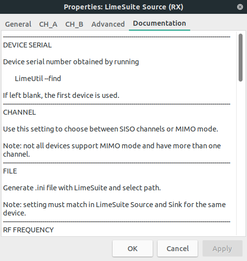
To use gr-limesdr blocks efficiently you can always double click on block, to open its settings and then check Documentation tab as in Figure 8 which can hint you what each setting does. The same applies to LimeSuite Source (RX) as well as LimeSuite Sink (TX).
Examples
FM transmitter
You can find FM transmitter example (FM_transmitter.grc) in gr-limesdr/examples directory. Open this example and you should see blocks as shown in Figure 9.
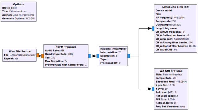
Here you can see six blocks:
- Options block is always used in GNU Radio flow graphs. From GNU Radio Wiki: In order to make a hierarchical block, the parameters in the options block must be set properly. The id of the options block sets the module name and must be unique among the entire library of blocks (built-in and custom). The title parameter sets the display name for the block. The generate options must be set to "Hier Block". The category parameter sets the category for the new block. This category can be an existing category in the block selection window or a new category.
- Wav file source is used to create data source from an audio wave file. In order for this example to work you should choose gr-limesdr/examples/piano.wav file. Audio rate should be 48kHz. Wav file source could be changed to Audio source in order to transmit real time recording device data.
- NBFM Transmit block stands for narrowband transmit. This block performs as FM modulator.
- Rational Resampler block is used to change sample rate of NBFM output in order to meet LimeSuite Sink (TX) input sample rate. NBFM output sample rate (480kS) is multiplied by 25 and divided by 6 (480 000*25/6 =2 000 000). The result is 2MS.
- LimeSuite Sink (TX) is used to consume (transmit) samples at 2MS.
- WX GUI FFT Sink is used to analyze FFT of samples produced for LimeSuite Sink (TX) to consume.
FM receiver
You can find FM receiver example (FM_receiver.grc) in gr-limesdr/examples directory. Open this example and you should see blocks as shown in Figure 10.
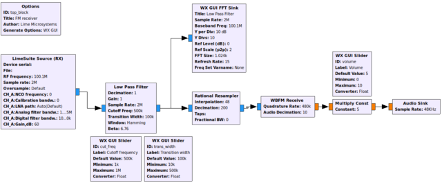
Here you can see eleven blocks:
- Options block is always used in GNU Radio flow graphs. From GNU Radio Wiki: In order to make a hierarchical block, the parameters in the options block must be set properly. The id of the options block sets the module name and must be unique among the entire library of blocks (built-in and custom). The title parameter sets the display name for the block. The generate options must be set to "Hier Block". The category parameter sets the category for the new block. This category can be an existing category in the block selection window or a new category.
- LimeSuite Source (RX) is used to produce (receive) samples at 2MS rate.
- Low Pass Filter filters unnecessary frequencies. Frequencies above 500kHz with transition width of 100kHz are filtered. Filter can be modified real time by using WX GUI Slider blocks in order to modify Cutoff Frequency and Transition Width.
- Rational Resampler block is used to change sample rate of Low Pass Filter output in order to meet WBFM Receive input sample rate. Low Pass Filter output sample rate (2MS) is multiplied by 48 and divided by 200 (2 000 000*48/200 =480 000). The result is 480kS.
- WBFM Receive stands for wideband FM receive. It acts as FM demodulator.
- Multiply const is used to adjust volume (amplitude) by using WX GUI Slider with Volume slider.
- Audio Sink is used to produce real time sound through playback device.
Resetting device after program is closed
In order to close device properly you should not use Kill the flow graph button in top bar of GNU Radio as it is shown in Figure 11. What it does is it kills process without calling gr-limesdr destructor which is necessary to perform stream close and device reset routines. Kill the flowgraph button could be useful if user wants to check registers and settings via LimeSuite and does not want to reset them while exiting GNU Radio flow graph process.

However it is possible to close device streams and reset device properly. This can be done by using WX GUI and pressing close WX GUI windows as shown in Figure 12.
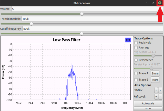
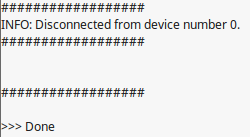
If device is closed properly you should always see “Disconnected from device number …” message as shown in Figure 13.
More information
| |||||||||||||||||||||