Gr-limesdr Plugin for GNURadio: Difference between revisions
| (6 intermediate revisions by one other user not shown) | |||
| Line 88: | Line 88: | ||
Visit this [http://www.gcndevelopment.com/gnuradio/downloads.htm link] and download GNU Radio binary for your system. Install GNU Radio from binary. | Visit this [http://www.gcndevelopment.com/gnuradio/downloads.htm link] and download GNU Radio binary for your system. Install GNU Radio from binary. | ||
After you installed GNU Radio download precompiled and zipped package by visiting this [https://downloads.myriadrf.org/project/limesuite/20. | After you installed GNU Radio download precompiled and zipped package by visiting this [https://downloads.myriadrf.org/project/limesuite/20.07/GNURadio3.7_windows_20.07.zip link] and extract it to GNU Radio installation directory. Usually GNU Radio installation directory is located in “C:\Program Files\GNURadio-3.7”. Now after restarting GNU Radio you should be able to use gr-limesdr package. | ||
=== Installing Pothos SDR dev environment which includes GNU Radio and gr-limesdr === | === Installing Pothos SDR dev environment which includes GNU Radio and gr-limesdr === | ||
| Line 327: | Line 327: | ||
On Windows you have to find the device through device manager, example is provided in Figure 12. | On Windows you have to find the device through device manager, example is provided in Figure 12. | ||
[[File: | [[File:RFE_device_manager_example.png|thumb|center|640px|Figure 12. Finding device with Device Manager]] | ||
* '''SDR DEVICE SERIAL''': This option appears when "SDR" communication is selected. Here you can provide the serial number of the device you are going to use. This list can be obtained by running following command in your Linux terminal window: | * '''SDR DEVICE SERIAL''': This option appears when "SDR" communication is selected. Here you can provide the serial number of the device you are going to use. This list can be obtained by running following command in your Linux terminal window: | ||
<pre> | <pre> | ||
| Line 370: | Line 370: | ||
=== FM receiver === | === FM receiver === | ||
You can find FM receiver example (FM_receiver.grc) in gr-limesdr/examples directory. Open this example and you should see blocks as shown in Figure | You can find FM receiver example (FM_receiver.grc) in gr-limesdr/examples directory. Open this example and you should see blocks as shown in Figure 15. | ||
[[File:FM_Receiver_Example_GnuRadio.png|thumb|center|640px|Figure | [[File:FM_Receiver_Example_GnuRadio.png|thumb|center|640px|Figure 15. FM receiver example]] | ||
| Line 382: | Line 382: | ||
* WBFM Receive stands for wideband FM receive. It acts as FM demodulator. | * WBFM Receive stands for wideband FM receive. It acts as FM demodulator. | ||
* Multiply const is used to adjust volume (amplitude) by using WX GUI Slider with Volume slider. | * Multiply const is used to adjust volume (amplitude) by using WX GUI Slider with Volume slider. | ||
* Audio Sink is used to produce real time sound through playback device. | * Audio Sink is used to produce real time sound through playback device. | ||
=== FM receiver with RDS === | === FM receiver with RDS === | ||
| Line 394: | Line 393: | ||
=== GFSK Loopback === | === GFSK Loopback === | ||
You can find GFSK loopback example (GFSK.grc) in gr-limesdr/examples directory. Open this example and you should see blocks as shown in Figure | You can find GFSK loopback example (GFSK.grc) in gr-limesdr/examples directory. Open this example and you should see blocks as shown in Figure 16. | ||
[[File:GFSK_loopback_example.png|thumb|center|640px|Figure | [[File:GFSK_loopback_example.png|thumb|center|640px|Figure 16. GFSK loopback example]] | ||
| Line 404: | Line 403: | ||
After data is sent we receive data by using “LimeSuite Source (RX)” and analyze it via “Quadrature Demod” and “QT GUI Time Sink”. “GFSK Demod” is used to extract packets who are decoded by using “Packet Decoder” and saved in file via “File Sink”. After we kill the flow graph we can analyze sent text data and received text data in order to see the results. | After data is sent we receive data by using “LimeSuite Source (RX)” and analyze it via “Quadrature Demod” and “QT GUI Time Sink”. “GFSK Demod” is used to extract packets who are decoded by using “Packet Decoder” and saved in file via “File Sink”. After we kill the flow graph we can analyze sent text data and received text data in order to see the results. | ||
=== Signal Generator === | === Signal Generator === | ||
You can find Signal Generator example (signal_generator.grc) in gr-limesdr/examples directory. Open this example and you should see blocks as shown in Figure | You can find Signal Generator example (signal_generator.grc) in gr-limesdr/examples directory. Open this example and you should see blocks as shown in Figure 17. | ||
[[File:Signal_generator_example.png|thumb|center|640px|Figure | [[File:Signal_generator_example.png|thumb|center|640px|Figure 17. Signal generator example]] | ||
Here we have signal generator example. By using “Signal Source” block we can generate different waveforms (constant, sine, cosine, square, triangle and saw tooth) with different frequencies and sampling rates. “Signal Source” block is connected directly to the “LimeSuite Sink (TX)” block which then transmits generated data. In order to see our wave form we use “QT GUI Sink” and spectate waterfall, FFT, time and constellation graphs. In order to configure device while running this flow graph we add baseband, TX gain, NCO frequency, NCO direction, analog and digital filters controls by using QT. This way we have powerful Signal Generator. To try Signal Analyzer and Signal Generator examples we can execute them in single flow graph and try to analyze sent and receive sample by creating loopback conditions with antennas or attenuators and cables. | Here we have signal generator example. By using “Signal Source” block we can generate different waveforms (constant, sine, cosine, square, triangle and saw tooth) with different frequencies and sampling rates. “Signal Source” block is connected directly to the “LimeSuite Sink (TX)” block which then transmits generated data. In order to see our wave form we use “QT GUI Sink” and spectate waterfall, FFT, time and constellation graphs. In order to configure device while running this flow graph we add baseband, TX gain, NCO frequency, NCO direction, analog and digital filters controls by using QT. This way we have powerful Signal Generator. To try Signal Analyzer and Signal Generator examples we can execute them in single flow graph and try to analyze sent and receive sample by creating loopback conditions with antennas or attenuators and cables. | ||
=== Signal Analyzer === | === Signal Analyzer === | ||
You can find Signal Analyzer example (signal_analyzer.grc) in gr-limesdr/examples directory. Open this example and you should see blocks as shown in Figure | You can find Signal Analyzer example (signal_analyzer.grc) in gr-limesdr/examples directory. Open this example and you should see blocks as shown in Figure 18. | ||
[[File:Signal_analyzer_example.png|thumb|center|640px|Figure | [[File:Signal_analyzer_example.png|thumb|center|640px|Figure 18. Signal analyzer example]] | ||
In this example we use “LimeSuite Source (RX)” to receive samples and analyze them by using “QT GUI Sink”. In “QT GUI Sink” we can see waterfall, constellation, time and FFT graphs. By using QT controls we can adjust RX gain, baseband, NCO, analog and digital filters. To try Signal Analyzer and Signal Generator examples we can execute them in single flow graph and try to analyze sent and received samples by creating loopback conditions with antennas or attenuators and cables. | In this example we use “LimeSuite Source (RX)” to receive samples and analyze them by using “QT GUI Sink”. In “QT GUI Sink” we can see waterfall, constellation, time and FFT graphs. By using QT controls we can adjust RX gain, baseband, NCO, analog and digital filters. To try Signal Analyzer and Signal Generator examples we can execute them in single flow graph and try to analyze sent and received samples by creating loopback conditions with antennas or attenuators and cables. | ||
=== Digital Video Broadcast DVB-T transmitter example === | === Digital Video Broadcast DVB-T transmitter example === | ||
| Line 430: | Line 426: | ||
A DVB-T terrestrial digital TV transmitter example (DVB_T_2k_64QAM_TX.grc) is provided in gr-limesdr/examples folder for testing. Transport stream file is quite big hence should be downloaded [http://www.w6rz.net/adv8dvbt23qam64.ts adv8dvbt23qam64.ts]. Place this file to gr-limesdr/examples folder. | A DVB-T terrestrial digital TV transmitter example (DVB_T_2k_64QAM_TX.grc) is provided in gr-limesdr/examples folder for testing. Transport stream file is quite big hence should be downloaded [http://www.w6rz.net/adv8dvbt23qam64.ts adv8dvbt23qam64.ts]. Place this file to gr-limesdr/examples folder. | ||
[[File:DVB-T_transmitter_example.png|thumb|center|640px|Figure | [[File:DVB-T_transmitter_example.png|thumb|center|640px|Figure 19. DVB-T transmitter example]] | ||
Latest revision as of 13:29, 29 July 2020
Introduction
LimeSDR is a low cost, open source software defined radio (SDR) platform that can be used to support just about any type of wireless communication standard. This document provides an overview of the installation process and operation of the gr-limesdr plugin for GNU Radio software. Currently this plugin supports LimeSDR-USB and LimeSDR-Mini boards.
Ubuntu Installation
This section covers gr-limesdr plugin installation instructions. Currently plugin is available for GNURadio 3.7 on Linux and Windows platforms and for GNURadio 3.8 on Linux.
Installing prerequisites
LimeSuite
Visit this link for information on how to install LimeSuite.
GNURadio
Visit this link for information on how to install GNU Radio.
Installing using Ubuntu package manager
Currently gr-limesdr plugin is packaged and available to download through Launchpad PPA:
sudo add-apt-repository ppa:myriadrf/gnuradio
sudo apt-get update
sudo apt-get install gr-limesdr
Installing from source
Installing dependencies
Enter the following command in terminal to install Boost and SWIG:
sudo apt-get install libboost-all-dev swig
If you installed GNURadio using package manager also download gnuradio-dev package:
sudo apt-get install gnuradio-dev
Building gr-limesdr from source
Downloading gr-limesdr source
Download gr-limesdr plugin by typing:
git clone https://github.com/myriadrf/gr-limesdr
Building and installing gr-limesdr from source
To build and install for GNURadio3.7 enter the following commands in terminal:
cd gr-limesdr
mkdir build
cd build
cmake ..
make
sudo make install
sudo ldconfig
For GNURadio3.8 these commands should be used:
cd gr-limesdr
git checkout gr-3.8
mkdir build
cd build
cmake ..
make
sudo make install
sudo ldconfig
Now you should reload GNU Radio blocks by restarting GNU Radio or by pressing Reload blocks button in top bar as seen in Figure 1. gr-limesdr blocks appear under LimeSuite category.

Windows installation
There are two options to install GNU Radio on Windows platform.
Installing only GNU Radio
Visit this link and download GNU Radio binary for your system. Install GNU Radio from binary.
After you installed GNU Radio download precompiled and zipped package by visiting this link and extract it to GNU Radio installation directory. Usually GNU Radio installation directory is located in “C:\Program Files\GNURadio-3.7”. Now after restarting GNU Radio you should be able to use gr-limesdr package.
Installing Pothos SDR dev environment which includes GNU Radio and gr-limesdr
Alternatively to paragraph 3.1 you can select this option and install the whole SDR development environment made by Pothos SDR which include LimeSuite, GNU Radio, gr-limesdr and other useful tools. Just visit this link and select “Download installer” option.
Device configuration
LimeSuite Sink (TX)
First you should pick LimeSuite Sink (TX) from LimeSuite category as shown in Figure 2.

LimeSuite Sink (TX) block appears in GNU Radio workspace as shown in Figure 3.
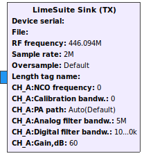
To configure block double click on it. Now you can see settings as shown in Figure 4.
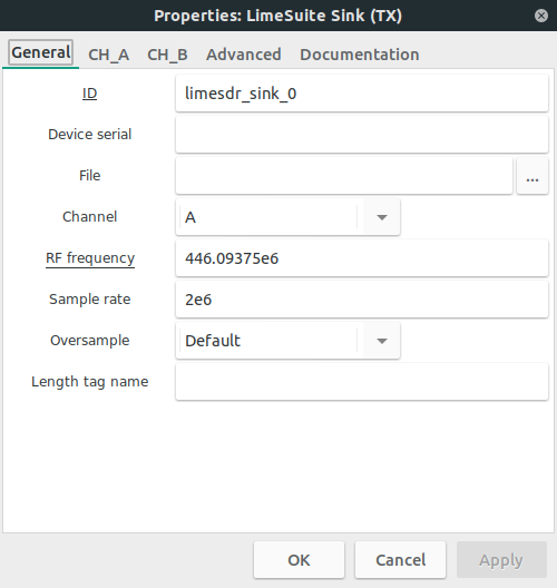
Available settings (in General, CH_A and CH_ tabs):
- ID: ID of current block in GNU Radio environment. This is usually left unchanged.
- Device serial: Select which device to use from a list of devices to use multiple devices. This list can be obtained by running following command in your Linux terminal window:
LimeUtil --find
- Channel: Use this setting to set single-input and single-output (SISO) or multiple-input and multiple-output (MIMO) chip mode. This setting enables/disables channels, sets correct number of streams and controls number of block inputs.
- In SISO mode you can select which channel to control (A or B).
- Note that not all boards (LimeSDR-Mini for instance) support MIMO mode.
- File: Select .ini file which you configured and saved by using LimeSuiteGUI. This setting should match in LimeSuite Sink (TX) and LimeSuite Source (RX) blocks for the same device.
- Note that Channel selection should match between LimeSuite Sink (TX) and LimeSuite Source (RX) blocks for the same device.
- RF frequency (callback function value): Set RF frequency for TX (both channels).
- LimeSDR-USB and LimeSDR-PCIe supports RF center frequency in range 100kHz–3.8GHz.
- LimeSDR-Mini supports RF center frequency in range 10MHz–3.5GHz.
- LimeNET-Micro supports RF center frequency in range 10MHz-3.5GHz
- Sample rate: Select sample rate for TX.
- LimeSDR-USB and LimeSDR-PCIe sample rate must be no more than 61.44 MS/s.
- LimeSDR-Mini sample rate must be no more than 30.72 MS/s.
- LimeNET-Micro sample rate must be no more than 10 MS/s.
- This setting should match in LimeSuite Sink (TX) and LimeSuite Source (RX) blocks for the same device.
- Oversample: Oversample lets you sample TX signal at a higher rate than would be required to just preserve the desired signal frequencies.
- Possible values (multipliers): Default (i.e. 0), 1, 2, 4, 8, 16, 32.
- Default value uses highest possible value based on other settings. Oversample is connected to sample rate (see Sample rate setting) and there are limitations as show in Table 1, Table 2 and Table 3. Note that LimeSDR-Mini and LimeNET-Micro supports only same oversampling for TX and RX.
| Sampling rate range (x) | Possible oversampling value |
|---|---|
| (15.36 < x ≤ 30.72) MS/s | 1, 2, 4 |
| (7.68 < x ≤ 15.36) MS/s | 1, 2, 4, 8 |
| (3.84 < x ≤ 7.86) MS/s | 1, 2, 4, 8, 16 |
| X ≤ 3.84 MS/s | 1, 2, 4, 8, 16, 32 |
| Sampling rate range (x) | Possible oversampling value |
|---|---|
| (30.72 < x ≤ 61.44) MS/s | 1, 2, 4, 8 |
| (15.36 < x ≤ 30.72) MS/s | 1, 2, 4, 8, 16 |
| X ≤ 15.36 MS/s | 1, 2, 4, 8, 16, 32 |
| Sampling rate range (x) | Possible oversampling value |
|---|---|
| (7.68 < x ≤ 10) MS/s | 1, 2, 4, 8 |
| (3.84 < x ≤ 7.86) MS/s | 1, 2, 4, 8, 16 |
| X ≤ 3.84 MS/s | 1, 2, 4, 8, 16, 32 |
- TCXO:DAC value: This setting modifies the VCTXCO DAC parameter value used to calibrate the reference clock. To enable this parameter "Allow TCXO DAC control" in the "Advanced" tab must be set to "Yes". Keep in mind that this parameter returns to its default value only after device power off.
- LimeSDR-Mini default value is 180 range is [0,255]
- LimeSDR-USB default value is 125 range is [0,255]
- LimeSDR-PCIe default value is 134 range is [0,255]
- LimeNET-Micro default value is 30714 range is [0,65535]
- Length tag name: Here you can set the name of incoming stream tag name. This tag is used to set how many samples are to be sent and it should be used in conjunction with “tx_time” tag to set the exact time samples should be sent. Position of length tag name tag tells where the burst starts and its value tells how many samples burst has. Length tag name’s value is an int64 and “tx_time” tag is pmt::cons pair which consist of two numbers: number of full seconds(int64) and number of fractional seconds(double). More about stream tags can be read here: link
- NCO frequency (callback function value): Here you can adjust numerically controlled oscillator. 0 means, that NCO is OFF.
- Calibration bandw.: This setting is used to set bandwidth for TX calibration of each channel. This value should be equal to your signal bandwidth. 0 means that calibration is OFF.
- Calibration bandwidth range must be 2.5MHz–120MHz.
- PA path (callback function value): Select active power amplifier path of each channel.
- Possible selections: Auto(Default),BAND1, BAND2.
- This setting also controls LimeSDR-Mini and LimeNET-Micro board path switch (BAND1/BAND2).
- When Auto(Default) is selected, RF path is automatically selected for LimeSDR-Mini and LimeNET-Micro boards depending on RF frequency. Auto(Default) sets BAND1 for LimeSDR-USB and LimeSDR-PCIe.
- Analog filter bandw. (callback function value): Enter TX analog filter bandwidth for each channel. 0 means that analog filter is turned OFF.
- TX analog filter bandwidth range must be 5MHz–130MHz.
- Digital filter bandw. (callback function value):Enter TX digital filter bandwidth for each channel. 0 means that digital filter is turned OFF.
- TX digital filter bandwidth should not be higher than sampling rate.
- Gain (callback function value): Controls TX channel gain.
- Gain range must be 0dB–73dB.
LimeSuite Source (RX)
First you should pick LimeSuite Source (RX) from LimeSuite category as shown in Figure 5.

LimeSuite Source (RX) block appears in GNU Radio workspace as shown in Figure 6.
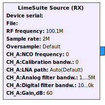
To configure block double click on it. Now you can see settings as shown in Figure 7.
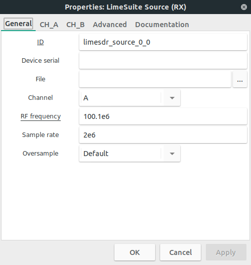
Available settings (in General, CH_A and CH_B tabs):
- ID: ID of current block in GNU Radio environment. This is usually left unchanged.
- Device number: Select which device to use from a list of devices to use multiple devices. This list can be obtained by running following command in your Linux terminal window:
LimeUtil --find
- Channel: Use this setting to set single-input and single-output (SISO) or multiple-input and multiple-output (MIMO) chip mode. This setting enables/disables channels, sets correct number of streams and controls number of block inputs.
- In SISO mode you can select which channel to control (A or B).
- Note that not all boards (LimeSDR-Mini for instance) support MIMO mode.
- File: Select .ini file which you configured and saved by using LimeSuiteGUI. This setting should match in LimeSuite Sink (TX) and LimeSuite Source (RX) blocks for the same device.
- Note that Channel selection should match between LimeSuite Sink (TX) and LimeSuite Source (RX) blocks for the same device. LimeSuite Source (RX) blocks for the same device.
- RF frequency (callback function value): Set RF frequency for RX (both channels).
- LimeSDR-USB and LimeSDR-PCIe supports RF center frequency in range 100kHz–3.8GHz.
- LimeSDR-Mini supports RF center frequency in range 10MHz–3.5GHz.
- LimeNET-Micro supports RF center frequency in range 10MHz-3.5GHz
- Sample rate: Select sample rate for RX.
- LimeSDR-USB and LimeSDR-PCIe sample rate must be no more than 61.44 MS/s.
- LimeSDR-Mini sample rate must be no more than 30.72 MS/s.
- LimeNET-Micro sample rate must be no more than 10 MS/s.
- This setting should match in LimeSuite Sink (TX) and LimeSuite Source (RX) blocks for the same device.
- Oversample: Oversample lets you sample RX signal at a higher rate than would be required to just preserve the desired signal frequencies.
- Possible values (multipliers): Default (i.e. 0), 1, 2, 4, 8, 16, 32.
- Default value uses highest possible value based on other settings. Oversample is connected to sample rate (see Sample rate setting) and there are limitations as show in Table 4, Table 5 and Table 6. Note that LimeSDR-Mini and LimeNET-Micro supports only same oversampling for TX and RX.
| Sampling rate range (x) | Possible oversampling value |
|---|---|
| (15.36 < x ≤ 30.72) MS/s | 1, 2, 4 |
| (7.68 < x ≤ 15.36) MS/s | 1, 2, 4, 8 |
| (3.84 < x ≤ 7.86) MS/s | 1, 2, 4, 8, 16 |
| X ≤ 3.84 MS/s | 1, 2, 4, 8, 16, 32 |
| Sampling rate range (x) | Possible oversampling value |
|---|---|
| (7.68 < x ≤ 10) MS/s | 1, 2, 4, 8 |
| (3.84 < x ≤ 7.86) MS/s | 1, 2, 4, 8, 16 |
| X ≤ 3.84 MS/s | 1, 2, 4, 8, 16, 32 |
| Sampling rate range (x) | Possible oversampling value |
|---|---|
| (30.72 < x ≤ 61.44) MS/s | 1, 2 |
| (15.36 < x ≤ 30.72) MS/s | 1, 2, 4 |
| (7.68 < x ≤ 15.36) MS/s | 1, 2, 4, 8 |
| (3.84 < x ≤ 7.86) MS/s | 1, 2, 4, 8, 16 |
| X ≤ 3.84 MS/s | 1, 2, 4, 8, 16, 32 |
- TCXO:DAC value: This setting modifies the VCTXCO DAC parameter value used to calibrate the reference clock. To enable this parameter "Allow TCXO DAC control" in the "Advanced" tab must be set to "Yes". Keep in mind that this parameter returns to its default value only after device power off.
- LimeSDR-Mini default value is 180 range is [0,255]
- LimeSDR-USB default value is 125 range is [0,255]
- LimeSDR-PCIe default value is 134 range is [0,255]
- LimeNET-Micro default value is 30714 range is [0,65535]
- NCO frequency (callback function value): Here you can adjust numerically controlled oscillator. 0 means, that NCO is OFF.
- Calibration bandw.: This setting is used to set bandwidth for TX calibration of each channel. This value should be equal to your signal bandwidth. 0 means that calibration is OFF.
- Calibration bandwidth range must be 2.5MHz–120MHz.
- LNA path (callback function value): Select active low-noise amplifier path of each channel.
- Auto(Default) for all boards.
- LimeSDR-USB and LimeSDR-PCIe possible selections: LNAH, LNAL, LNAW.
- LimeSDR-Mini possible selections: LNAH, LNAW.
- LimeSDR-Micro possible selections: LNAH, LNAL.
- This setting also controls LimeSDR-Mini and LimeNET-Micro board path switch.
- When Auto(Default) is selected, LNA path is automatically selected for LimeSDR-Mini and LimeNET-Micro boards depending on RF frequency. Auto(Default) sets LNAH for LimeSDR-USB and LimeSDR-PCIe.
- Analog filter bandw. (callback function value): Enter RX analog filter bandwidth for each channel. 0 means that analog filter is turned OFF.
- RX analog filter bandwidth range must be 1.5MHz–130MHz.
- Digital filter bandw. (callback function value):Enter RX digital filter bandwidth for each channel. 0 means that digital filter is turned OFF.
- RX digital filter bandwidth should not be higher than sampling rate.
- Gain (callback function value): Controls RX channel gain.
- Gain range must be 0dB–73dB.
LimeSuite Source (RX) also transmits “rx_time” tag which tells when exactly samples have been received. It is pmt::cons pair which consist of two numbers: number of full seconds(int64) and number of fractional seconds(double). This tag is transmitted whenever the stream is started or interrupted. More about stream tags can be read here: link
LimeRFE Control
First you should pick LimeRFE Control block from LimeSuite category as shown in Figure 8.

LimeRFE Control block appears in GNU Radio workspace as shown in Figure 9.
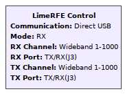
To configure block double click on it. Now you can see settings as shown in Figure 10.
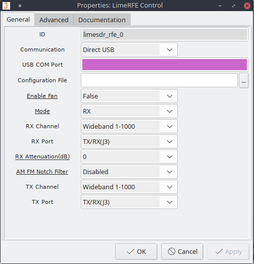
Available settings:
- ID: ID of current block in GNU Radio environment. This is usually left unchanged.
- Communication: Select how LimeRFE device will be connected, available options are:
- Direct USB: LimeRFE is configured directly through USB COM port
- SDR: LimeRFE is configured through LimeSDR device GPIO ports
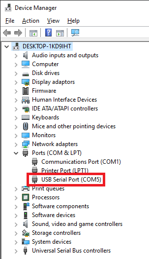
- USB COM PORT: This option appears when "Direct USB" communication is selected. Here you need to type the COM port LimeRFE device is connected to. On Linux you can find the COM port by using dmesg command, example is shown in Figure 11.

- Note, in the settings you need to type "/dev/ttyUSB0" instead of just "ttyUSB0"
- Note, with only one serial device connected you can find it by typing "ls /dev/ttyUSB*" command in the terminal
On Windows you have to find the device through device manager, example is provided in Figure 12.
- SDR DEVICE SERIAL: This option appears when "SDR" communication is selected. Here you can provide the serial number of the device you are going to use. This list can be obtained by running following command in your Linux terminal window:
LimeUtil --find
- Note That this option can be left blank and first device in the list will be used.
- Note LimeSDR device needs to be connected to LimeRFE through GPIO for it to work.
- Configuration File: If set LimeRFE device will be configured using already generated .ini file
- Note: .ini file must be generated using LimeSuite->Modules->LimeRFE->save, general LimeSuite .ini file will not work
- Enable Fan (callback function value): Enable or disable fan connected to LimeRFE device
- Mode (callback function value): With this option LimeRFE device mode is set.
- Possible selections: RX(0), TX(1), RX+TX(2), NONE(3)
- RX Channel: Select RX channel to be configured, if Cellular Bands are selected, the same channel is set for TX.
- RX Port: Select hardware port to be used for receive, to know which Channels are compatible with which ports, please see the documentation link.
- RX Attenuation (callback function value): Specifies the attenuation in the RX path. Attenuation [dB] = 2 * attenuation.
- AM FM NOTCH FILTER (callback function value): Enables or disables AM FM notch filter, please see documentation for which channels attenuation is available.
- TX Channel: Select TX channel to be configured, this option is hidden if Cellular bands for RX are selected.
- TX Port: Select hardware port to be used for transmit, to know which Channels are compatible with which ports, please see the documentation link.
Documentation tab
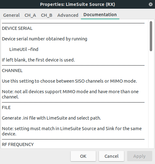
To use gr-limesdr blocks efficiently you can always double click on block, to open its settings and then check Documentation tab as in Figure 13 which can hint you what each setting does. The same applies to all provided GNURadio blocks
Examples
FM transmitter
You can find FM transmitter example (FM_transmitter.grc) in gr-limesdr/examples directory. Open this example and you should see blocks as shown in Figure 14.
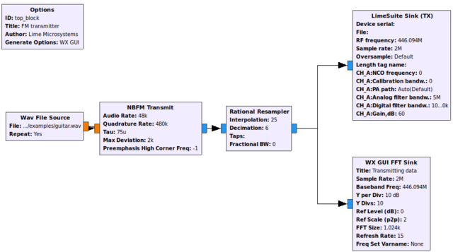
Here you can see six blocks:
- Options block is always used in GNU Radio flow graphs. From GNU Radio Wiki: In order to make a hierarchical block, the parameters in the options block must be set properly. The id of the options block sets the module name and must be unique among the entire library of blocks (built-in and custom). The title parameter sets the display name for the block. The generate options must be set to "Hier Block". The category parameter sets the category for the new block. This category can be an existing category in the block selection window or a new category.
- Wav file source is used to create data source from an audio wave file. In order for this example to work you should choose gr-limesdr/examples/piano.wav file. Audio rate should be 48kHz. Wav file source could be changed to Audio source in order to transmit real time recording device data.
- NBFM Transmit block stands for narrowband transmit. This block performs as FM modulator.
- Rational Resampler block is used to change sample rate of NBFM output in order to meet LimeSuite Sink (TX) input sample rate. NBFM output sample rate (480kS) is multiplied by 25 and divided by 6 (480 000*25/6 =2 000 000). The result is 2MS.
- LimeSuite Sink (TX) is used to consume (transmit) samples at 2MS.
- WX GUI FFT Sink is used to analyze FFT of samples produced for LimeSuite Sink (TX) to consume.
FM receiver
You can find FM receiver example (FM_receiver.grc) in gr-limesdr/examples directory. Open this example and you should see blocks as shown in Figure 15.
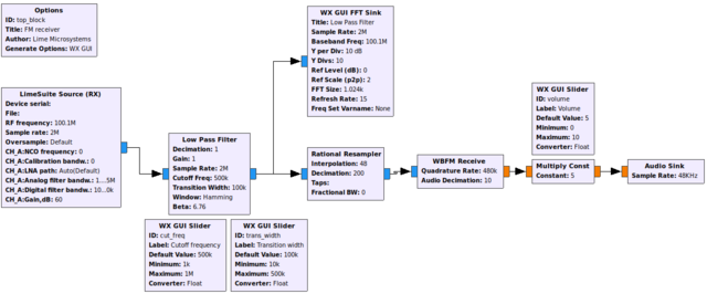
Here you can see eleven blocks:
- Options block is always used in GNU Radio flow graphs. From GNU Radio Wiki: In order to make a hierarchical block, the parameters in the options block must be set properly. The id of the options block sets the module name and must be unique among the entire library of blocks (built-in and custom). The title parameter sets the display name for the block. The generate options must be set to "Hier Block". The category parameter sets the category for the new block. This category can be an existing category in the block selection window or a new category.
- LimeSuite Source (RX) is used to produce (receive) samples at 2MS rate.
- Low Pass Filter filters unnecessary frequencies. Frequencies above 500kHz with transition width of 100kHz are filtered. Filter can be modified real time by using WX GUI Slider blocks in order to modify Cutoff Frequency and Transition Width.
- Rational Resampler block is used to change sample rate of Low Pass Filter output in order to meet WBFM Receive input sample rate. Low Pass Filter output sample rate (2MS) is multiplied by 48 and divided by 200 (2 000 000*48/200 =480 000). The result is 480kS.
- WBFM Receive stands for wideband FM receive. It acts as FM demodulator.
- Multiply const is used to adjust volume (amplitude) by using WX GUI Slider with Volume slider.
- Audio Sink is used to produce real time sound through playback device.
FM receiver with RDS
You can find advanced FM receiver example based on “gr-rds” package example (rds_rx.grc) in gr-limesdr/examples directory. Before using this example you should install “gr-rds” package link.
To understand how this flow graph works read the following articles: link 1 link 2
GFSK Loopback
You can find GFSK loopback example (GFSK.grc) in gr-limesdr/examples directory. Open this example and you should see blocks as shown in Figure 16.
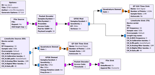
Here you can see both GFSK modulation and GFSK demodulation parts to show realtime data processing by using single LimeSDR board. Ensure that you have antennas connected to your board or you may use attenuator instead.
Choose your data source in block “File Source”. The data may containt text that you are about to send. “Packet Encoder” is used to add logical structure to raw bytes. The block takes as many bytes as Payload Length is defined and groups them with header and CNC which when left blank uses default values. “GFSK Mod” block performs GFSK modulation and then samples are sent by using “LimeSuite Sink (TX)”. We use “Quadrature Demod” block in order to convert complex samples to I and Q floating point sample stream and analyze them in “QT GUI Time Sink”.
After data is sent we receive data by using “LimeSuite Source (RX)” and analyze it via “Quadrature Demod” and “QT GUI Time Sink”. “GFSK Demod” is used to extract packets who are decoded by using “Packet Decoder” and saved in file via “File Sink”. After we kill the flow graph we can analyze sent text data and received text data in order to see the results.
Signal Generator
You can find Signal Generator example (signal_generator.grc) in gr-limesdr/examples directory. Open this example and you should see blocks as shown in Figure 17.

Here we have signal generator example. By using “Signal Source” block we can generate different waveforms (constant, sine, cosine, square, triangle and saw tooth) with different frequencies and sampling rates. “Signal Source” block is connected directly to the “LimeSuite Sink (TX)” block which then transmits generated data. In order to see our wave form we use “QT GUI Sink” and spectate waterfall, FFT, time and constellation graphs. In order to configure device while running this flow graph we add baseband, TX gain, NCO frequency, NCO direction, analog and digital filters controls by using QT. This way we have powerful Signal Generator. To try Signal Analyzer and Signal Generator examples we can execute them in single flow graph and try to analyze sent and receive sample by creating loopback conditions with antennas or attenuators and cables.
Signal Analyzer
You can find Signal Analyzer example (signal_analyzer.grc) in gr-limesdr/examples directory. Open this example and you should see blocks as shown in Figure 18.
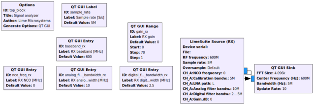
In this example we use “LimeSuite Source (RX)” to receive samples and analyze them by using “QT GUI Sink”. In “QT GUI Sink” we can see waterfall, constellation, time and FFT graphs. By using QT controls we can adjust RX gain, baseband, NCO, analog and digital filters. To try Signal Analyzer and Signal Generator examples we can execute them in single flow graph and try to analyze sent and received samples by creating loopback conditions with antennas or attenuators and cables.
Digital Video Broadcast DVB-T transmitter example
A DVB-T terrestrial digital TV transmitter example (DVB_T_2k_64QAM_TX.grc) is provided in gr-limesdr/examples folder for testing. Transport stream file is quite big hence should be downloaded adv8dvbt23qam64.ts. Place this file to gr-limesdr/examples folder.
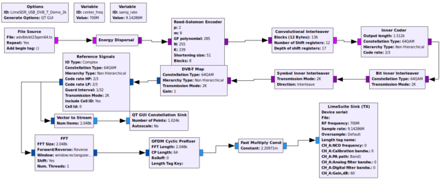
To run the example, you may connect your LimeSDR-USB (or LimeSDR-Mini) to an RTLSDR dongle (while using it in DVB mode) or any other USB DVB receiver. Simply connect the output marked TX-1 (TX on LimeSDR-Mini) to your DVB-T dongle's RF input using a coaxial cable (or by connecting separate antennas to both devices). Before running the example project, you need to double click on the file source block and select the adv8dvbt23qam64.ts test transfer stream file, which should be placed in the gr-limesdr/examples folder. You may then use VLC Media Player (https://www.videolan.org/) at the receiving end to display the digital TV stream by running it with the following command:
vlc dvb://frequency=700000
This will set up VLC to receive a DVB-T data stream transmitted with a carrier frequency of 700MHz.
Note: you need a fairly capable CPU for realtime encoding and transmission of a DVB-T stream. Lack of processing power for stream encoding and transmission usualy results in the received video stream stuttering, random glitches or losing audio (typically accompanied by VLC's 'TS Discontinuity' errors in the terminal).
Various tools, additional information and links to variant bitrate test streams for the DVB-T flow graphs can be found here: https://github.com/drmpeg/dtv-utils
More information
| |||||||||||||||||||||