Uncategorized files
Jump to navigation
Jump to search
Showing below up to 94 results in range #501 to #594.
-
 RBB register setup procedure.png 1,004 × 600; 147 KB
-
 RFDIO-Card-Connector-1.jpg 375 × 287; 16 KB
-
 RFDIO-Figure1.jpg 843 × 384; 29 KB
-
 RFDIO-Figure2.jpg 1,338 × 446; 56 KB
-
 RFDIO-Figure3.jpg 551 × 395; 24 KB
-
 RFE Control.png 183 × 88; 6 KB
-
 RFE Settings.png 503 × 523; 36 KB
-
 RFE block.png 182 × 136; 5 KB
-
 RFE device manager example.png 303 × 525; 24 KB
-
 RFE dmesg example.png 670 × 127; 39 KB
-
 RX DC offset manual calibration.png 1,186 × 707; 203 KB
-
 Rasdr2-case-inside.jpg 1,632 × 1,224; 687 KB
-
 Rasdr2-case-montage-cropped.jpg 2,405 × 2,810; 795 KB
-
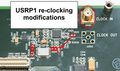 Re-clocking.jpg 840 × 500; 80 KB
-
 Receiver spectrum with un-calibrated IQ imbalance.png 987 × 564; 108 KB
-
 Reload Blocks Button GnuRadio.png 458 × 37; 8 KB
-
 Rx IQ correction block.png 1,178 × 700; 318 KB
-
 SNOWLeoSDR.jpg 1,024 × 639; 125 KB
-
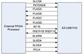 STREAM-Board-GPIF-II.jpg 475 × 314; 20 KB
-
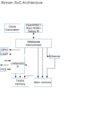 STREAM-OpenRISC-Block-Diagram.png 794 × 1,123; 67 KB
-
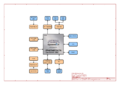 STREAM-Schematics-1.png 3,508 × 2,480; 303 KB
-
 STREAM-Schematics-10.png 3,508 × 2,480; 264 KB
-
 STREAM-Schematics-11.png 3,508 × 2,480; 350 KB
-
 STREAM-Schematics-12.png 3,508 × 2,480; 205 KB
-
 STREAM-Schematics-13.png 3,508 × 2,480; 318 KB
-
 STREAM-Schematics-14.png 3,508 × 2,480; 467 KB
-
 STREAM-Schematics-15.png 3,508 × 2,480; 721 KB
-
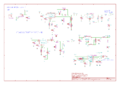
 STREAM-Schematics-2.png 3,508 × 2,480; 704 KB
-
 STREAM-Schematics-3.png 3,508 × 2,480; 571 KB
-
 STREAM-Schematics-4.png 3,508 × 2,480; 613 KB
-
 STREAM-Schematics-5.png 3,508 × 2,480; 296 KB
-
 STREAM-Schematics-6.png 3,508 × 2,480; 436 KB
-
 STREAM-Schematics-7.png 3,508 × 2,480; 402 KB
-
 STREAM-Schematics-8.png 3,508 × 2,480; 248 KB
-
 STREAM-Schematics-9.png 3,508 × 2,480; 237 KB
-
 STREAM.jpg 722 × 522; 114 KB
-
 SXR SXT register setup procedure.png 1,005 × 599; 189 KB
-
 SatHelperApp 1 768w.jpg 768 × 768; 267 KB
-
 ScratchRadio-AddExtension1.jpg 242 × 285; 20 KB
-
 ScratchRadio-AddExtension2.jpg 882 × 306; 33 KB
-
 ScratchRadio-AddExtension3.jpg 667 × 107; 18 KB
-
 ScratchRadio-ExamplesDirectory.jpg 595 × 480; 48 KB
-
 ScratchRadio-FlowIconProcess.jpg 43 × 57; 8 KB
-
 ScratchRadio-FlowIconSink.jpg 42 × 58; 8 KB
-
 ScratchRadio-FlowIconSource.jpg 44 × 60; 8 KB
-
 ScratchRadio-FlowIconTap.jpg 41 × 59; 8 KB
-
 ScratchRadio-MessageLoopbackExample1.jpg 276 × 272; 24 KB
-
 ScratchRadio-MessageLoopbackExample2.jpg 316 × 234; 21 KB
-
 ScratchRadio-MessageLoopbackExample3.jpg 388 × 188; 21 KB
-
 ScratchRadio-MessageLoopbackExample4.jpg 261 × 187; 15 KB
-
 ScratchRadio-ParallelFlowGraphExample.jpg 377 × 297; 34 KB
-
 ScratchRadio-RadioLifecycle.jpg 266 × 183; 20 KB
-
 ScratchRadio-RadioRunningStatus.jpg 540 × 182; 26 KB
-
 ScratchRadio-SimpleFlowGraphExample.jpg 369 × 250; 28 KB
-
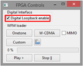 Select Digital Loopback enable.png 454 × 363; 56 KB
-
 Selecting FPGA Control window.png 375 × 409; 65 KB
-
 Selecting LimeSuiteGUI settings file.png 487 × 364; 68 KB
-
 Sending LMS7002M settings to GUI.png 497 × 245; 37 KB
-
 Sending LMS7002M settings to LimeSDR-USB board.png 503 × 250; 39 KB
-
 Setting data type to Packets MIMO.png 490 × 365; 66 KB
-
 Si5351C configuration window.png 1,007 × 519; 114 KB
-
 Signal analyzer example.png 955 × 321; 62 KB
-
 Signal generator example.png 1,104 × 358; 94 KB
-
 Successfully FX3 programing message.png 900 × 212; 66 KB
-
 TBB register setup procedure.png 1,004 × 598; 175 KB
-
 Tamer-gui-buttons.png 630 × 55; 4 KB
-
 Tamer-gui-fosc-fout.png 630 × 81; 8 KB
-
 Tamer-gui-gps.png 630 × 134; 10 KB
-
 Tamer-gui-hwi-ver.png 630 × 76; 8 KB
-
 Tamer-gui-outputs.png 630 × 86; 7 KB
-
 Tamer-gui-pic.png 630 × 299; 280 KB
-
 Tamer-gui-small.png 162 × 200; 38 KB
-
 Tamer-gui.png 630 × 778; 366 KB
-
 TrinityCollege s1r1.jpg 306 × 408; 66 KB
-
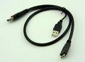 USB3 cable.jpg 700 × 505; 69 KB
-
 Ubuntu logo.png 77 × 80; 3 KB
-
 Unclaimed-pvr-windows.png 960 × 150; 7 KB
-
 Visual studio logo.png 148 × 57; 6 KB
-
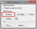 Waveform selection.png 454 × 365; 55 KB
-
 Weatherdump alpha3 demo.png 1,085 × 660; 286 KB
-
 Windows logo.png 80 × 80; 9 KB
-
 Zipper-1.jpg 777 × 632; 217 KB
-
 Zipper-Block-Diagram.jpg 929 × 637; 126 KB
-
 Zipper-Connections-Bottom.jpg 717 × 557; 68 KB
-
 Zipper-Connections-Top.jpg 704 × 554; 66 KB
-
 Zipper-Interface-Board-Schematics-1.png 2,480 × 3,508; 255 KB
-
 Zipper-Interface-Board-Schematics-2.png 2,480 × 3,508; 326 KB
-
 Zipper-Interface-Board-Schematics-3.png 2,480 × 3,508; 256 KB
-
 Zipper-Interface-Board-Schematics-4.png 2,480 × 3,508; 207 KB
-
 Zipper-Interface-Board-Schematics-5.png 2,480 × 3,508; 181 KB
-
 Zipper-Interface-Board-Schematics-6.png 2,480 × 3,508; 393 KB
-
 Zipper-Interface-Board-Schematics-7.png 2,480 × 3,508; 288 KB
-
 Zipper-Interface-Board-Schematics-8.png 2,480 × 3,508; 143 KB
-
 Zipper-J2.jpg 462 × 931; 71 KB


