Uncategorized files
Jump to navigation
Jump to search
Showing below up to 20 results in range #121 to #140.
-
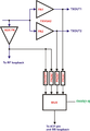
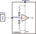 LMS6002D-PLL-Reference-Clock-Input-Buffer-DC-Coupled.png 1,820 × 1,734; 95 KB
-
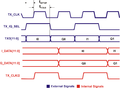
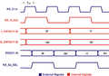 LMS6002D-RX-Data-Interface-Signals.png 2,338 × 1,637; 151 KB
-
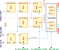
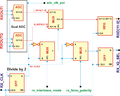 LMS6002D-RX-Data-Interface.png 1,909 × 1,533; 192 KB
-
 LMS6002D-RX-Gain-Control-Architecture.png 1,581 × 602; 109 KB
-
 LMS6002D-SPI-Read-Cycle-3-Wire.png 4,916 × 909; 200 KB
-
 LMS6002D-SPI-Read-Cycle-4-Wire.png 4,927 × 1,271; 230 KB
-
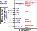 LMS6002D-SPI-Supplies.png 1,157 × 972; 115 KB
-
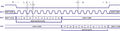
 LMS6002D-SPI-Write-Cycle.png 4,916 × 881; 189 KB
-
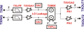
 LMS6002D-TX-Data-Interface.png 1,743 × 1,481; 190 KB
-
 LMS6002D-TX-Gain-Control-Architecture.png 1,575 × 550; 91 KB
-
 LMS6002D-TX-IQ-Interface-Signals.png 2,327 × 1,700; 150 KB
-
 LMS6002D-Typical-Application-Circuit-RF-Part.png 683 × 730; 41 KB
-
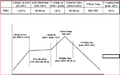 LMS6002D FAQ Ramp Rate.png 639 × 397; 37 KB
-
 LMS6002D FAQ VCO Frequency Range.png 1,399 × 743; 29 KB
-
 LMS6002Dr2-DC-Offset-Calibration-LPF-Tuning-Module.png 427 × 650; 19 KB
-
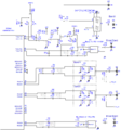
 LMS6002Dr2-Envelop-Pick-Detector.png 1,868 × 2,699; 146 KB
-
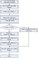
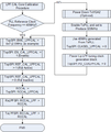
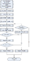 LMS6002Dr2-General-DC-Calibration.png 382 × 780; 20 KB
-
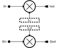 LMS6002Dr2-IQ-Gain-Correction.png 223 × 184; 5 KB
-
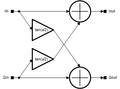 LMS6002Dr2-IQ-Phase-Correction.png 340 × 252; 7 KB
-
 LMS6002Dr2-LPF-Bandwidth-Tuning.png 521 × 620; 26 KB


