Uncategorized files
Jump to navigation
Jump to search
Showing below up to 100 results in range #101 to #200.
-
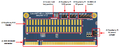
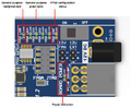 Figure 9 LimeSDR-QPCIe v1.2 indication LEDs.png 463 × 382; 120 KB
-
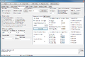
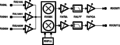
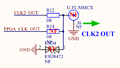 Figure 9 SMA connector J6 source selection.png 1,336 × 759; 70 KB
-
 Freebsd-128-128.png 132 × 128; 36 KB
-
 Freebsd-logo.png 178 × 175; 32 KB
-
 GFSK loopback example.png 990 × 481; 105 KB
-
 Git logo.png 155 × 80; 4 KB
-
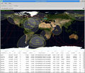 Gpredict 1 768w.jpg 768 × 656; 164 KB
-
 Grc xmit only.jpg 781 × 246; 39 KB
-
 IQ Corrector block control.png 1,186 × 708; 243 KB
-
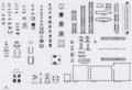 KiCAD footprints.png 700 × 478; 321 KB
-
 Kill Flow Graph Button GnuRadio.png 141 × 36; 4 KB
-
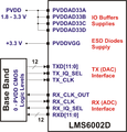
 LMS6002D-Baseband-Data-Interface.png 1,324 × 1,149; 121 KB
-
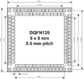 LMS6002D-DQFN120-Package-Top-View.png 1,386 × 1,298; 153 KB
-
 LMS6002D-Digital-IQ-Interface-Supplies.png 1,146 × 1,196; 155 KB
-
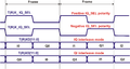 LMS6002D-Frame-Sync-Polarity-Interleave-Modes.png 2,262 × 1,210; 166 KB
-
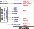
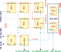
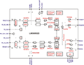 LMS6002D-Functional-Block-Diagram.png 3,149 × 2,425; 475 KB
-
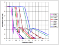 LMS6002D-LPF-Amplitude-Response-1.png 706 × 546; 34 KB
-
 LMS6002D-LPF-Amplitude-Response-2.png 706 × 546; 34 KB
-
 LMS6002D-PLL-Architecture.png 1,927 × 1,446; 106 KB
-
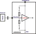 LMS6002D-PLL-Reference-Clock-Input-Buffer-AC-Coupled.png 1,820 × 1,734; 95 KB
-
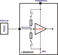 LMS6002D-PLL-Reference-Clock-Input-Buffer-DC-Coupled.png 1,820 × 1,734; 95 KB
-
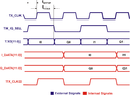
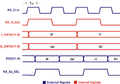 LMS6002D-RX-Data-Interface-Signals.png 2,338 × 1,637; 151 KB
-
 LMS6002D-RX-Data-Interface.png 1,909 × 1,533; 192 KB
-
 LMS6002D-RX-Gain-Control-Architecture.png 1,581 × 602; 109 KB
-
 LMS6002D-SPI-Read-Cycle-3-Wire.png 4,916 × 909; 200 KB
-
 LMS6002D-SPI-Read-Cycle-4-Wire.png 4,927 × 1,271; 230 KB
-
 LMS6002D-SPI-Supplies.png 1,157 × 972; 115 KB
-
 LMS6002D-SPI-Write-Cycle.png 4,916 × 881; 189 KB
-
 LMS6002D-TX-Data-Interface.png 1,743 × 1,481; 190 KB
-
 LMS6002D-TX-Gain-Control-Architecture.png 1,575 × 550; 91 KB
-
 LMS6002D-TX-IQ-Interface-Signals.png 2,327 × 1,700; 150 KB
-
 LMS6002D-Typical-Application-Circuit-RF-Part.png 683 × 730; 41 KB
-
 LMS6002D FAQ Ramp Rate.png 639 × 397; 37 KB
-
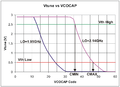
 LMS6002D FAQ VCO Frequency Range.png 1,399 × 743; 29 KB
-
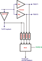
 LMS6002Dr2-DC-Offset-Calibration-LPF-Tuning-Module.png 427 × 650; 19 KB
-
 LMS6002Dr2-Envelop-Pick-Detector.png 1,868 × 2,699; 146 KB
-
 LMS6002Dr2-General-DC-Calibration.png 382 × 780; 20 KB
-
 LMS6002Dr2-IQ-Gain-Correction.png 223 × 184; 5 KB
-
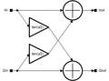 LMS6002Dr2-IQ-Phase-Correction.png 340 × 252; 7 KB
-
 LMS6002Dr2-LPF-Bandwidth-Tuning.png 521 × 620; 26 KB
-
 LMS6002Dr2-Loopback-Test.png 3,000 × 1,898; 539 KB
-
 LMS6002Dr2-PLL-Control.png 2,572 × 1,705; 201 KB
-
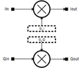
 LMS6002Dr2-RX-I-Q-DC-Level-Correction.png 265 × 207; 6 KB
-
 LMS6002Dr2-RXFE-Control.png 3,000 × 2,619; 590 KB
-
 LMS6002Dr2-RXVGA2-Control.png 2,517 × 1,696; 292 KB
-
 LMS6002Dr2-RXVGA2-DC-Offset-Calibration.png 793 × 627; 45 KB
-
 LMS6002Dr2-TXRF-Control.png 3,465 × 2,678; 444 KB
-
 LMS6002Dr2-TXRX-LPF-Control.png 1,390 × 1,110; 158 KB
-
 LMS6002Dr2-TXRX-LPF-DC-Offset-Calibration.png 424 × 760; 25 KB
-
 LMS6002Dr2-VCO-Capacitance-Selection.png 2,287 × 1,659; 178 KB
-
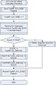
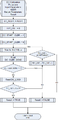
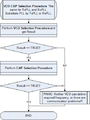 LMS6002Dr2-VCO-VCOCAP-Code-Selection-Algorithm-General.png 401 × 535; 17 KB
-
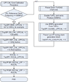
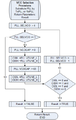 LMS6002Dr2-VCO-VCOCAP-Code-Selection-Algorithm-VCO-Selection.png 410 × 650; 20 KB
-
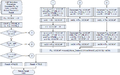 LMS6002Dr2-VCO-VCOCAP-Code-Selection-Algorithm-VCOCAP-Selection.png 926 × 582; 39 KB
-
 LMS7002M-1024w.jpg 1,024 × 682; 95 KB
-
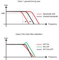 LMS7002Mr3Cal Analog filter tuning.jpg 688 × 701; 39 KB
-
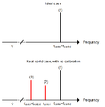
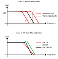 LMS7002Mr3Cal Analog filter tuning.png 796 × 813; 30 KB
-
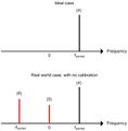 LMS7002Mr3Cal RX spectral tones.jpg 688 × 701; 23 KB
-
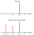 LMS7002Mr3Cal RX spectral tones.png 688 × 701; 12 KB
-
 LMS7002Mr3Cal TX spectral tones.jpg 688 × 701; 25 KB
-
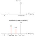
 LMS7002Mr3Cal TX spectral tones.png 699 × 713; 14 KB
-
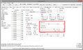
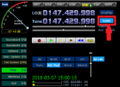
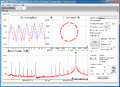 LMS Suite FFTviewer.png 931 × 676; 74 KB
-
 LMS Suite LMS6002RxPLL.png 892 × 601; 76 KB
-
 LTE5MHz 6MHz.gif 1,020 × 767; 59 KB
-
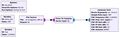
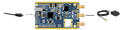 Lime-GPSDO Getting started Figure 1 Basic setup.png 3,587 × 911; 1.01 MB
-
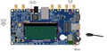
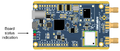 Lime-GPSDO Getting started Figure 2 Board status indication.png 2,074 × 879; 744 KB
-
-
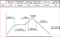
 Lime-GPSDO Getting started Figure 4 VCOCXO tune state log.png 661 × 344; 16 KB
-
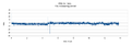
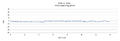
 Lime-GPSDO Getting started Figure 5 PPB vs Time, 1s measuring period.png 999 × 340; 112 KB
-
-
-
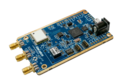 Lime-GPSDO v1.0.png 2,120 × 1,411; 2.53 MB
-
 LimeMicrosystems 167x70.jpg 167 × 70; 5 KB
-
 LimeNET-Micro 2.1 Communication interfaces.png 3,500 × 1,968; 286 KB
-
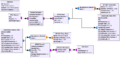
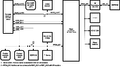
 LimeNET-Micro 2.1 Development Board Block Diagram.png 3,000 × 2,879; 106 KB
-
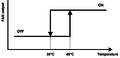 LimeNET-Micro 2.1 FAN control temperature hysteresis.png 1,730 × 835; 23 KB
-
 LimeNET-Micro 2.1 Fan connection to J8 header.png 4,420 × 2,085; 5.28 MB
-
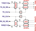
 LimeNET-Micro 2.1 LMS7002M RF path.png 3,000 × 887; 44 KB
-
 LimeNET-Micro 2.1 Lime-GPSDO board clock distribution block diagram.png 3,500 × 2,027; 75 KB
-
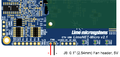
 LimeNET-Micro 2.1 Power rail selection for pin 10 of J5 connector.png 827 × 620; 101 KB
-
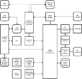
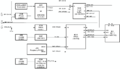
 LimeNET-Micro 2.1 board power distribution block diagram.png 3,500 × 1,630; 64 KB
-
 LimeNET-Micro 2.1 internal USB subsystem.png 3,000 × 1,282; 276 KB
-
 LimeNET-Micro Bottom side components.png 3,500 × 1,942; 2.31 MB
-
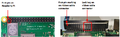
 LimeNET-Micro SODIMM adapter Figure 2.png 969 × 383; 130 KB
-
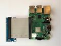
 LimeNET-Micro SODIMM adapter Figure 3.png 765 × 233; 241 KB
-
 LimeNET-Micro SODIMM adapter Figure 4.jpg 5,005 × 3,753; 1.97 MB
-
 LimeNET-Micro top side components and connectors.png 3,500 × 2,208; 2.29 MB
-
LimeNET-Micro v2.1 diagrams v05 LED indicators of RJ45 (J9) connector.png 8,835 × 2,345; 2.14 MB
-
 LimeNET-Micro v2.1 diagrams v05 USB2 Host.png 2,041 × 976; 847 KB
-
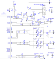
 LimeSDR-CORE SDR 1v1 schematic r0.PDF ; 5.41 MB
-
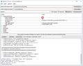 LimeSDR-ExtIO CMake Configuration.png 624 × 501; 109 KB
-
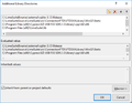
 LimeSDR-ExtIO CMake configuration example.png 1,425 × 650; 79 KB
-
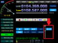
 LimeSDR-ExtIO HDSDR ExtIO button.png 505 × 367; 47 KB
-
 LimeSDR-ExtIO HDSDR RF gain slider.png 491 × 365; 45 KB
-
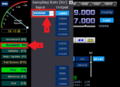 LimeSDR-ExtIO HDSDR sampling rate settings.png 503 × 365; 45 KB
-
 LimeSDR-ExtIO Include directories paths.png 571 × 444; 18 KB
-
 LimeSDR-ExtIO Library directory paths.png 571 × 444; 24 KB
-
 LimeSDR-ExtIO Main dialog panel.png 445 × 298; 14 KB
-
 LimeSDR-ExtIO RX gain control architecture.png 800 × 301; 56 KB
-
 LimeSDR-ExtIO build configuration.png 457 × 106; 41 KB
-
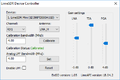
 LimeSDR-ExtIO cmake configuration.png 693 × 649; 41 KB


_connector.png)