Uploads by Ghalfacree
Jump to navigation
Jump to search
This special page shows all uploaded files.
| Date | Name | Thumbnail | Size | Description | Versions |
|---|---|---|---|---|---|
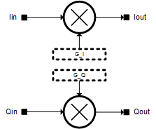
| 15:44, 13 October 2015 | LMS6002Dr2-IQ-Gain-Correction.png (file) |  |
5 KB | Improved graphic. | 2 |
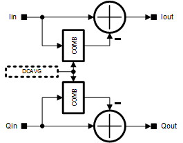
| 15:43, 13 October 2015 | LMS6002Dr2-RX-I-Q-DC-Level-Correction.png (file) |  |
6 KB | Improved graphic. | 2 |
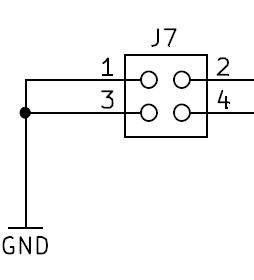
| 16:41, 16 July 2015 | DE0-Nano-J7.jpg (file) |  |
6 KB | DE0-Nano Interface Board J7. | 1 |
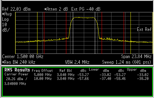
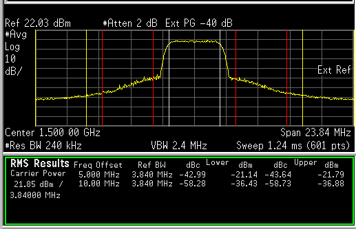
| 22:55, 3 June 2017 | Adpd-test-case-2-acpr-with-adpd.png (file) |  |
7 KB | ADPD test case 2, ACRP with ADPD. | 1 |
| 22:55, 3 June 2017 | Adpd-test-case-2-acpr-without-adpd.png (file) |  |
7 KB | ADPD test case 2, ACPR without ADPD. | 1 |
| 15:44, 13 October 2015 | LMS6002Dr2-IQ-Phase-Correction.png (file) |  |
7 KB | Improved graphic. | 2 |
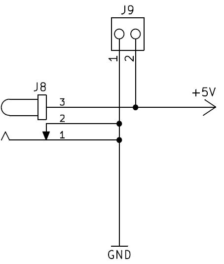
| 16:42, 16 July 2015 | DE0-Nano-J8-J9.jpg (file) |  |
12 KB | DE0-Nano Interface Board J8 and J9. | 1 |
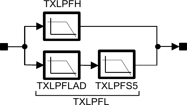
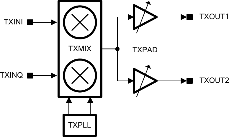
| 14:28, 2 June 2016 | Lms7002m-tx-analogue-filter-chain.png (file) |  |
13 KB | LMS7002M TX analogue filter chain diagram. | 1 |
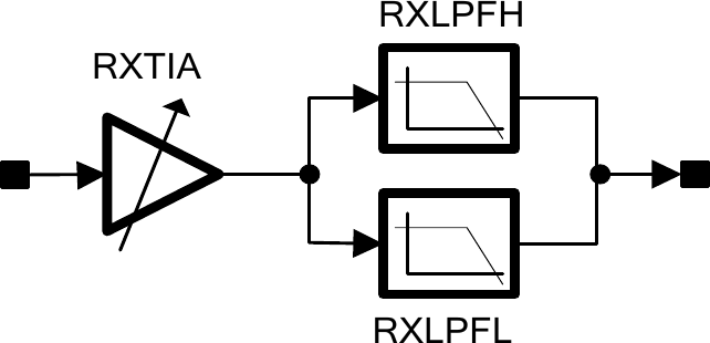
| 14:32, 2 June 2016 | Lms7002m-rx-analogue-filter-chain.png (file) |  |
13 KB | LMS7002M RX analogue filter chain diagram. | 1 |
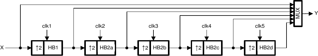
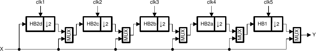
| 15:51, 2 June 2016 | Lms7002m-tsp-interpolation-filters.png (file) | 14 KB | LMS7002M interpolation filters diagram. | 1 | |
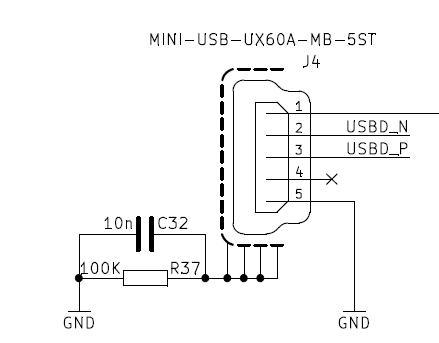
| 16:37, 16 July 2015 | DE0-Nano-J4.jpg (file) |  |
15 KB | DE0-Nano Interface Board J4, mini-USB connector. | 1 |
| 15:16, 2 June 2016 | Lms7002m-tsp-dc-offset.png (file) |  |
15 KB | LMS7002M DC offset diagram. | 1 |
| 16:14, 2 June 2016 | Lms7002m-tsp-decimation-filters.png (file) | 15 KB | LMS7002M decimation filter chain diagram. | 1 | |
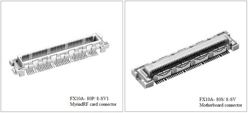
| 15:57, 13 July 2015 | RFDIO-Card-Connector-1.jpg (file) |  |
16 KB | The card-side Hirose connector for the RFDIO interface. | 1 |
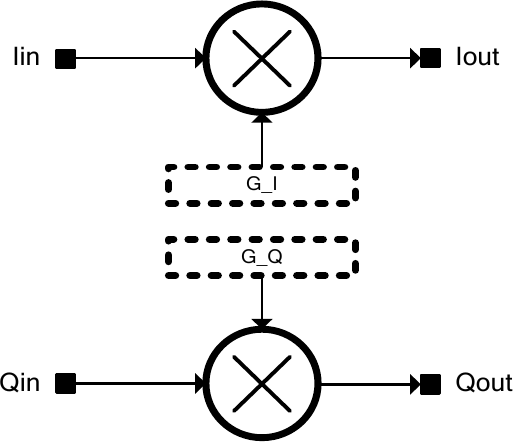
| 14:59, 2 June 2016 | Lms7002m-tsp-iq-gain-correction.png (file) |  |
17 KB | LMS7002M IQ gain correction diagram. | 1 |
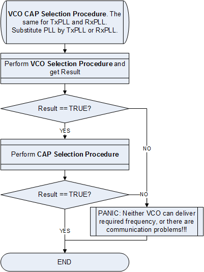
| 14:53, 6 October 2015 | LMS6002Dr2-VCO-VCOCAP-Code-Selection-Algorithm-General.png (file) |  |
17 KB | Clearer image. | 2 |
| 16:39, 16 July 2015 | DE0-Nano-J6.jpg (file) |  |
18 KB | DE0-Nano Interface Board J6 | 1 |
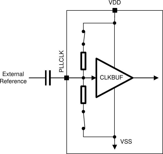
| 16:05, 1 June 2016 | Lms7002m-pll-reference-clock-input-buffer-ac-coupled.png (file) |  |
18 KB | LMS7002M PLL reference clock input buffer, AC coupled. | 1 |
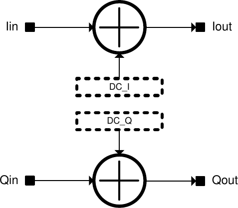
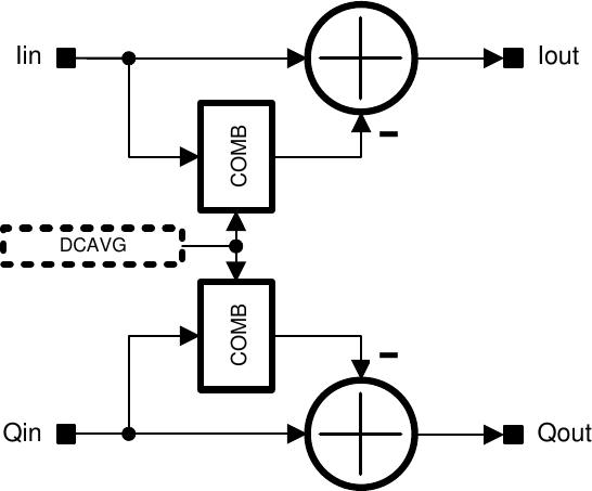
| 15:21, 2 June 2016 | Lms7002m-tsp-rx-dc-correction.png (file) |  |
18 KB | LMS7002M RX DC correction diagram. | 1 |
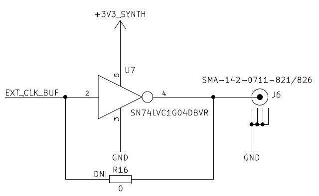
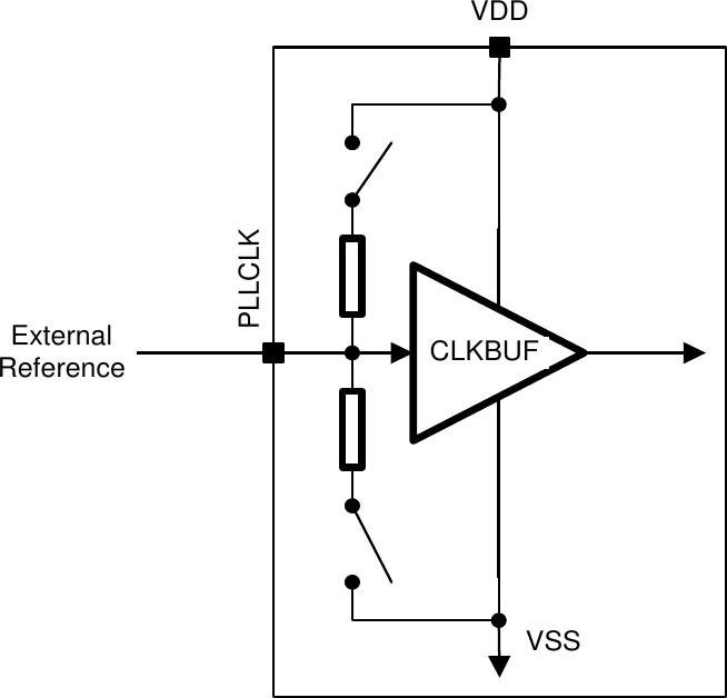
| 16:04, 1 June 2016 | Lms7002m-pll-reference-clock-input-buffer-dc-coupled.png (file) |  |
18 KB | LMS7002M PLL reference clock input buffer, DC coupled. | 1 |
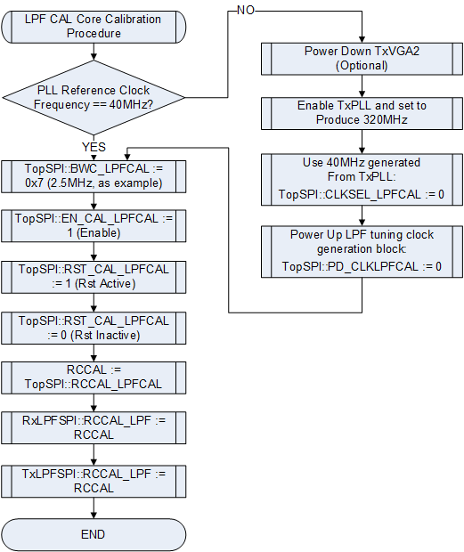
| 14:51, 6 October 2015 | LMS6002Dr2-DC-Offset-Calibration-LPF-Tuning-Module.png (file) |  |
19 KB | Higher resolution version. | 2 |
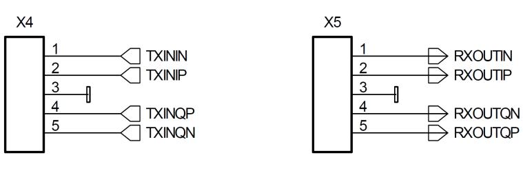
| 15:53, 16 July 2015 | MyriadRF1-X4-X5.jpg (file) |  |
19 KB | Myriad-RF 1 Board X4 and X5 connector pin-outs. | 1 |
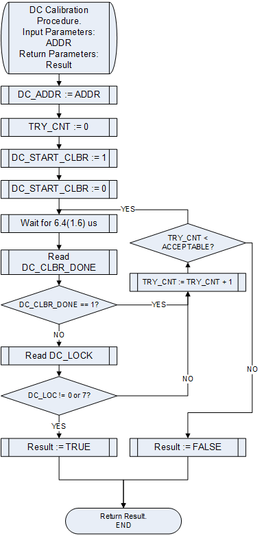
| 15:40, 13 October 2015 | LMS6002Dr2-General-DC-Calibration.png (file) |  |
20 KB | Updated diagram. | 2 |
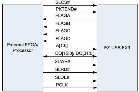
| 16:29, 22 July 2015 | STREAM-Board-GPIF-II.jpg (file) |  |
20 KB | STREAM Board GPIF II-related connections between FX3 and FPGA. | 1 |
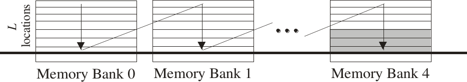
| 16:25, 2 June 2016 | Lms7002m-tsp-fir-memory-banks.png (file) | 20 KB | LMS7002M FIR memory bank diagram. | 1 | |
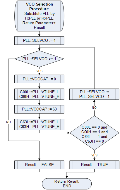
| 15:45, 13 October 2015 | LMS6002Dr2-VCO-VCOCAP-Code-Selection-Algorithm-VCO-Selection.png (file) |  |
20 KB | Improved graphic. | 2 |
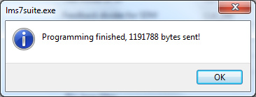
| 19:38, 4 May 2016 | LimeSDR-USB-LMS-7-Suite-Modules-Programming-Complete.jpg (file) |  |
20 KB | LMS 7 Suite confirming programming of an FPGA with a new bitstream. | 1 |
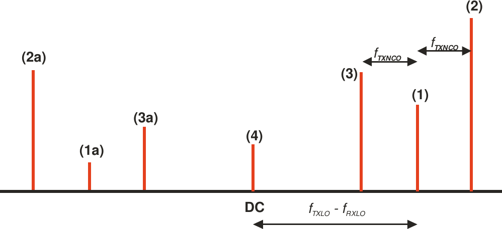
| 21:03, 2 June 2016 | Lms7002m-calibration-iq-imbalance-spectral-tones.png (file) |  |
20 KB | LMS7002M calibration, IQ imbalance spectral tones example | 1 |
| 16:01, 1 June 2016 | Lms7002m-pll-architecture.png (file) |  |
23 KB | LMS7002M PLL architecture diagram. | 1 |
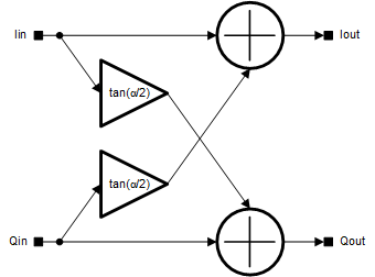
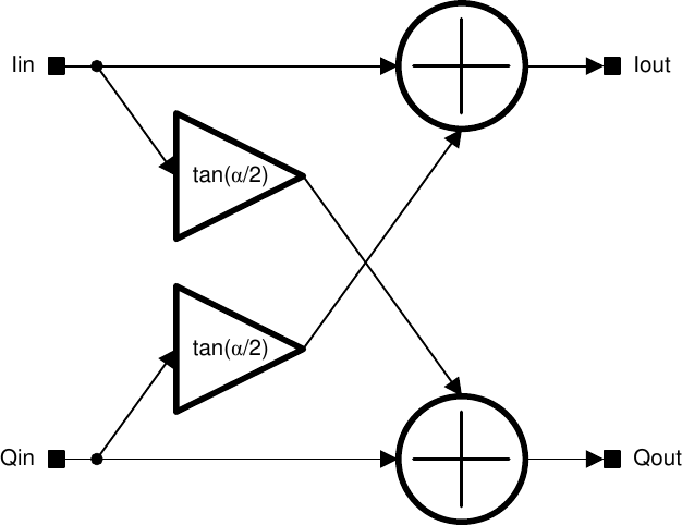
| 15:08, 2 June 2016 | Lms7002m-tsp-iq-phase-correction.png (file) |  |
24 KB | LMS7002M IQ phase correction diagram. | 1 |
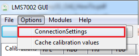
| 19:28, 4 May 2016 | LimeSDR-USB-LMS7002-GUI-ConnectionSettings.jpg (file) |  |
24 KB | LMS7002 GUI software showing ConnectionSettings option in Options menu. | 1 |
| 13:37, 16 July 2015 | RFDIO-Figure3.jpg (file) |  |
24 KB | Figure 3 from the RFDIO Connector Specification, Revision 1.0.1. | 1 |
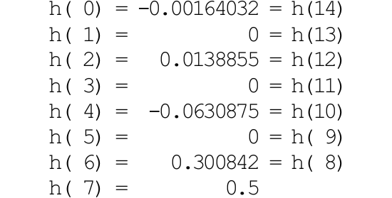
| 16:11, 2 June 2016 | Lms7002m-tsp-hb2-impulse-response.png (file) |  |
25 KB | LMS7002M HB2 impulse response figures. | 1 |
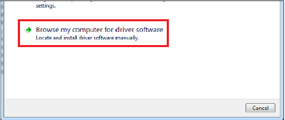
| 20:38, 3 May 2016 | LimeSDR-USB-Windows-USB-Driver-Installation-3.jpg (file) |  |
25 KB | LimeSDR-USB Windows driver installation, step 3. | 1 |
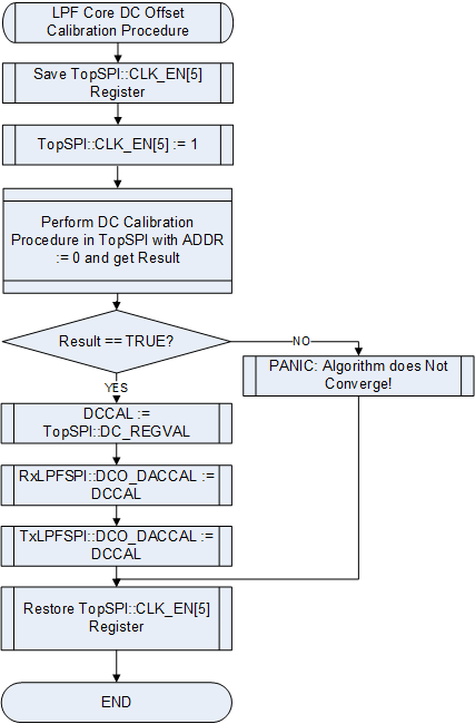
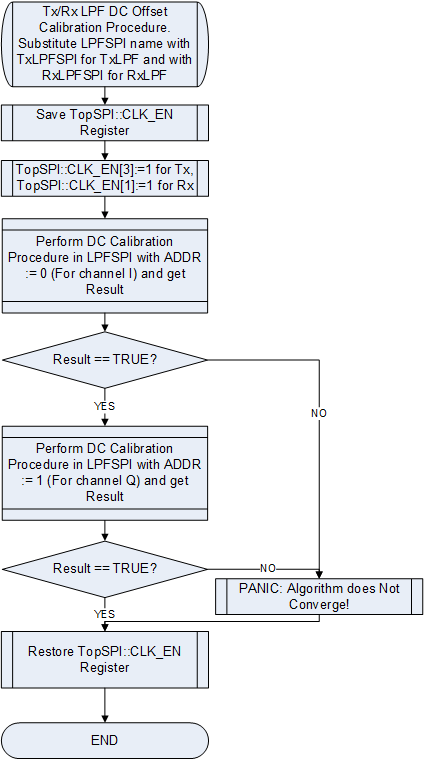
| 14:52, 6 October 2015 | LMS6002Dr2-TXRX-LPF-DC-Offset-Calibration.png (file) |  |
25 KB | Clearer image. | 2 |
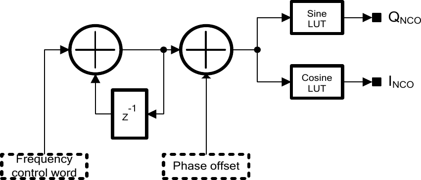
| 15:48, 2 June 2016 | Lms7002m-tsp-nco-architecture.png (file) |  |
25 KB | LMS7002M NCO architecture diagram. | 1 |
| 15:50, 1 June 2016 | Lms7002m-analogue-gain-control-architecture.png (file) |  |
26 KB | LMS7002M analogue/RF gain control architecture diagram. | 1 |
| 14:52, 6 October 2015 | LMS6002Dr2-LPF-Bandwidth-Tuning.png (file) |  |
26 KB | Clearer image. | 2 |
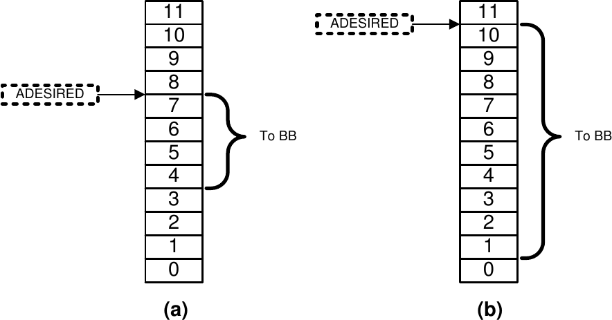
| 17:00, 2 June 2016 | Lms7002m-tsp-agc-truncation.png (file) |  |
28 KB | LMS7002M AGC truncation application example diagram. | 1 |
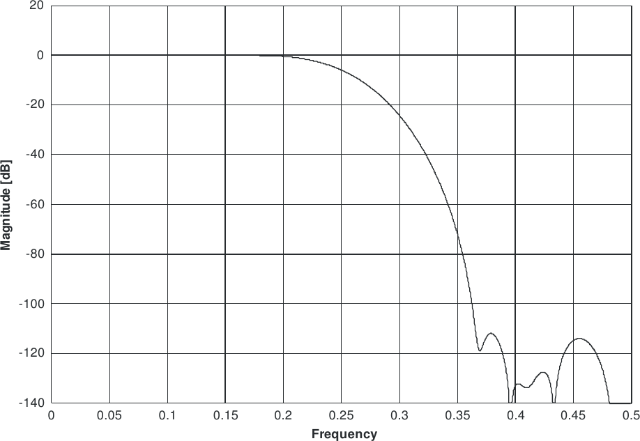
| 16:10, 2 June 2016 | Lms7002m-tsp-hb1-amplitude-response.png (file) |  |
28 KB | LMS7002M HB1 amplitude response graph. | 1 |
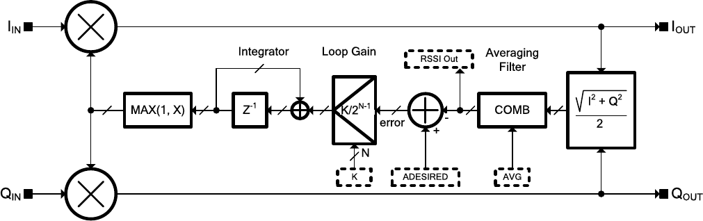
| 16:54, 2 June 2016 | Lms7002m-tsp-agc.png (file) |  |
28 KB | LMS7002M automatic gain control architecture diagram. | 1 |
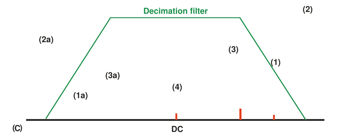
| 21:14, 2 June 2016 | Lms7002m-calibration-digital-filtering-step-c.png (file) |  |
29 KB | LMS7002M calibration, digital filtering step (c) | 1 |
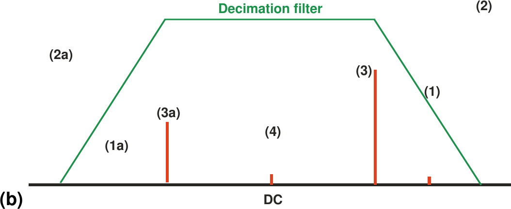
| 21:10, 2 June 2016 | Lms7002m-calibration-digital-filtering-step-b.png (file) |  |
29 KB | LMS7002M calibration, digital filtering step (b) | 1 |
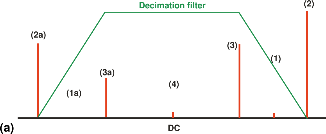
| 21:10, 2 June 2016 | Lms7002m-calibration-digital-filtering-step-a.png (file) |  |
29 KB | LMS7002M calibration, digital filtering step (a) | 1 |
| 13:31, 16 July 2015 | RFDIO-Figure1.jpg (file) |  |
29 KB | Figure 1 from the RFDIO Connector Specification, Revision 1.0.1. | 1 |
| 17:08, 2 June 2016 | Lms7002m-limelight-trxiq-rx-mode.png (file) |  |
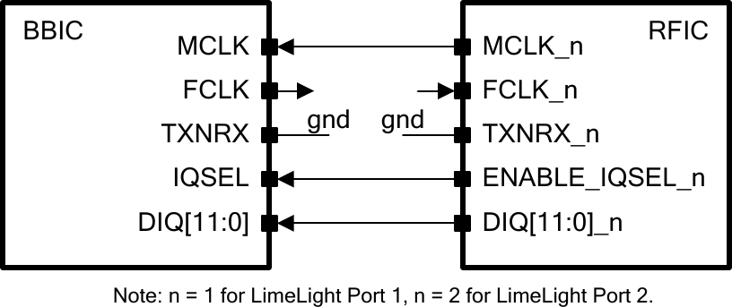
30 KB | LMS7002M LimeLight port, TRIXIQ-RX mode. | 1 |
| 17:03, 2 June 2016 | Lms7002m-limelight-jesd-mode.png (file) |  |
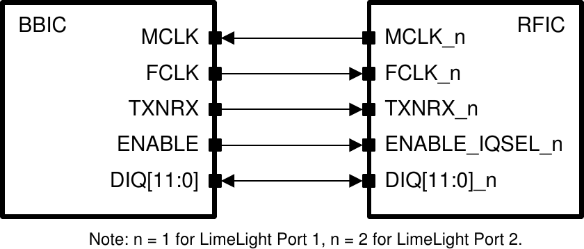
31 KB | LMS7002 LimeLight port in JESD mode. | 1 |
| 17:08, 2 June 2016 | Lms7002m-limelight-trxiq-tx-mode.png (file) |  |
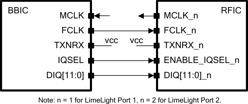
32 KB | LMS7002M LimeLight port, TRIXIQ-TX mode. | 1 |
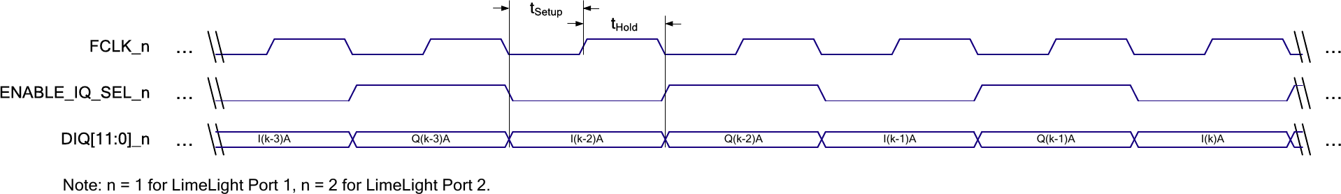
| 17:23, 2 June 2016 | Lms7002m-limelight-trxiq-sdr-transmit-data-path.png (file) | 32 KB | LMS7002M LimeLight TRXIQ SDR mode transmit data path timing diagram. | 1 | |
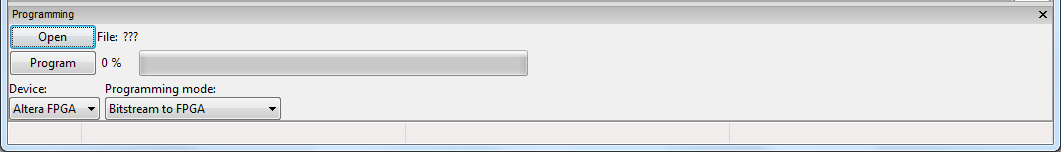
| 19:36, 4 May 2016 | LimeSDR-USB-LMS-7-Suite-Modules-Programming-Section.jpg (file) | 33 KB | LMS 7 Suite showing the programming section. | 1 |