Uploads by Ghalfacree
Jump to navigation
Jump to search
This special page shows all uploaded files.
| Date | Name | Thumbnail | Size | Description | Versions |
|---|---|---|---|---|---|
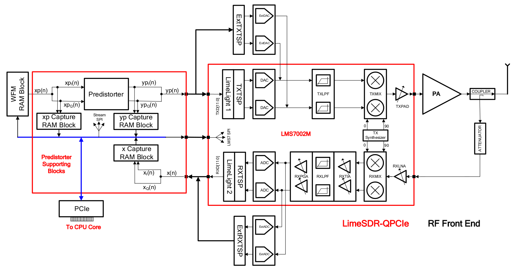
| 22:17, 3 June 2017 | Adpd-implementation-on-limesdr-qpcie-board-block-diagram.png (file) |  |
158 KB | An ADPD implementation block diagram, based on the LimeSDR-QPCIe board. | 1 |
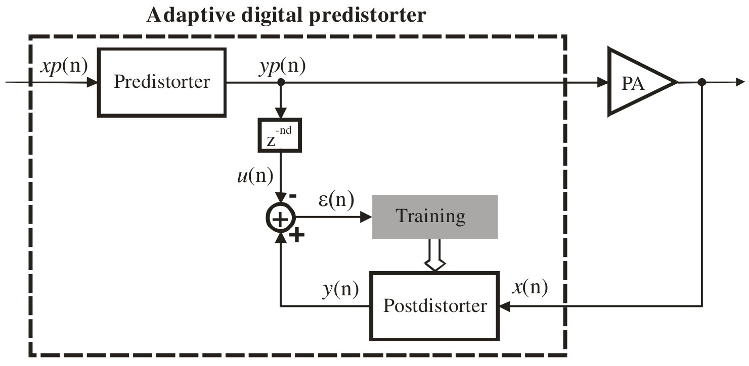
| 15:30, 3 June 2017 | Adpd-indirect-learning-architecture-block-diagram.png (file) |  |
60 KB | ADPD indirect learning architecture, block diagram. | 1 |
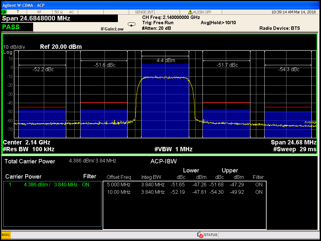
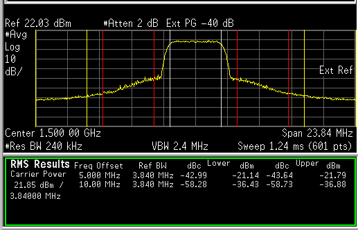
| 22:50, 3 June 2017 | Adpd-test-case-1-acpr-with-adpd.png (file) |  |
37 KB | ADPD test case 1, ACPR with ADPD. | 1 |
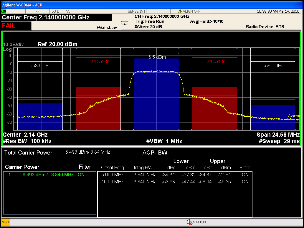
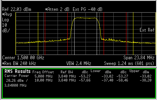
| 22:48, 3 June 2017 | Adpd-test-case-1-acpr-without-adpd.png (file) |  |
37 KB | ADPD test case 1, ACPR without ADPD. | 1 |
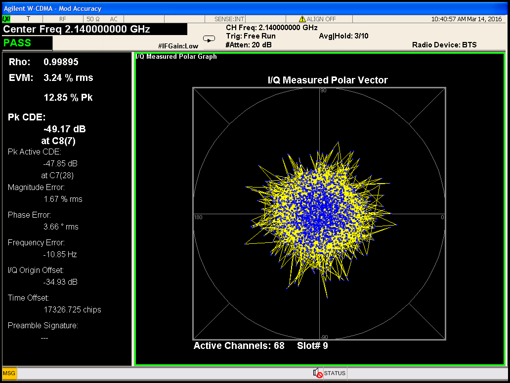
| 22:52, 3 June 2017 | Adpd-test-case-1-evm-with-adpd.png (file) |  |
52 KB | ADPD test case 1, EVM with ADPD. | 1 |
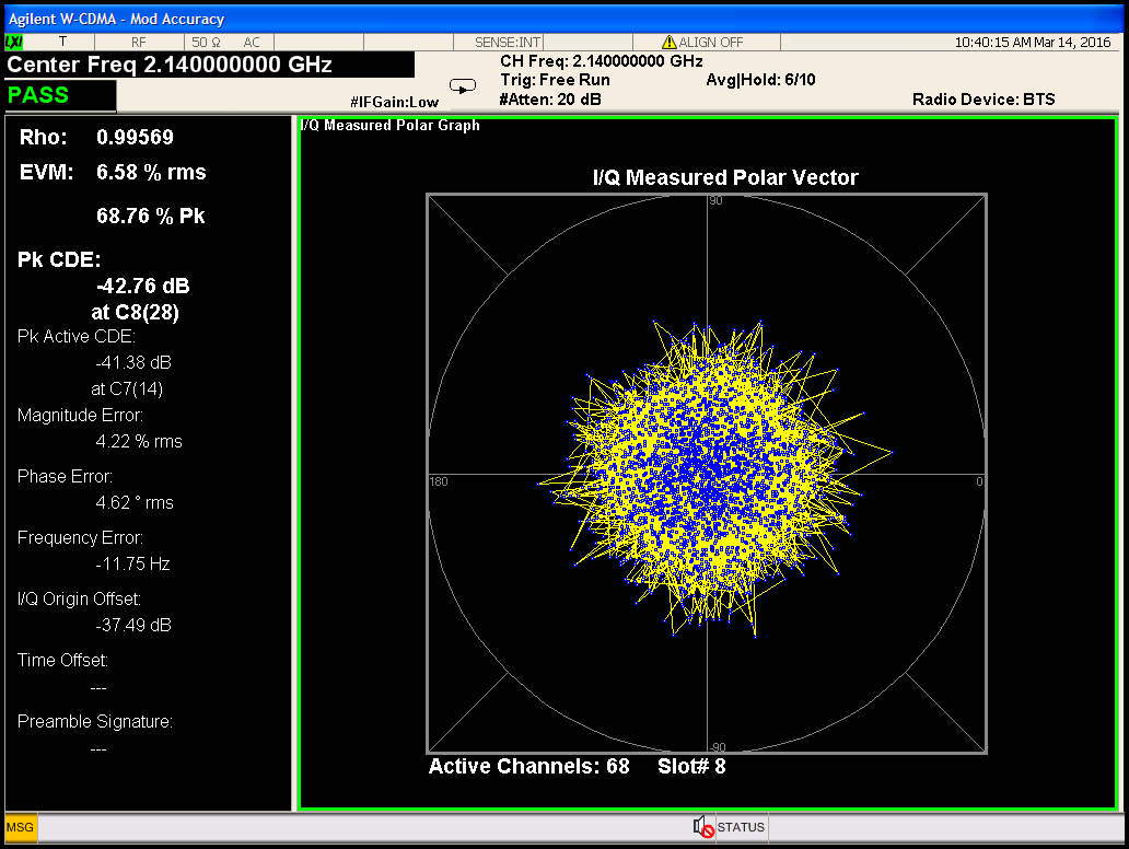
| 22:51, 3 June 2017 | Adpd-test-case-1-evm-without-adpd.png (file) |  |
53 KB | ADPD test case 1, EVM without ADPD. | 1 |
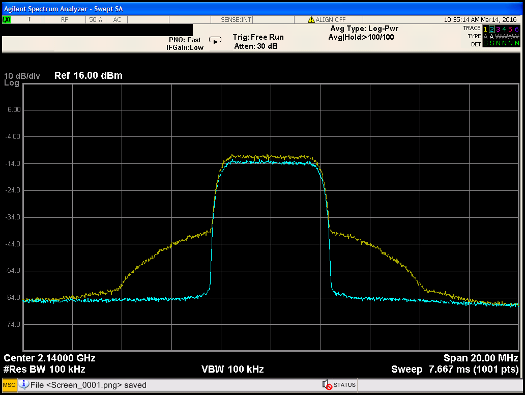
| 22:46, 3 June 2017 | Adpd-test-case-1-pa-output-spectrum.png (file) |  |
35 KB | ADPD test case 1, PA output spectrum. | 1 |
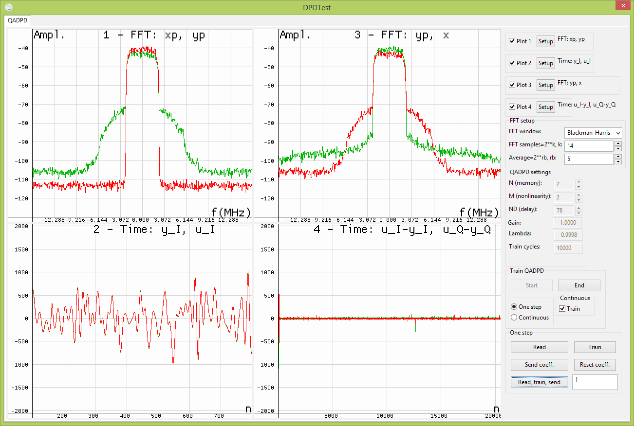
| 22:44, 3 June 2017 | Adpd-test-case-1-signals-after-training.png (file) |  |
47 KB | ADPD test case 1, signals after training. | 1 |
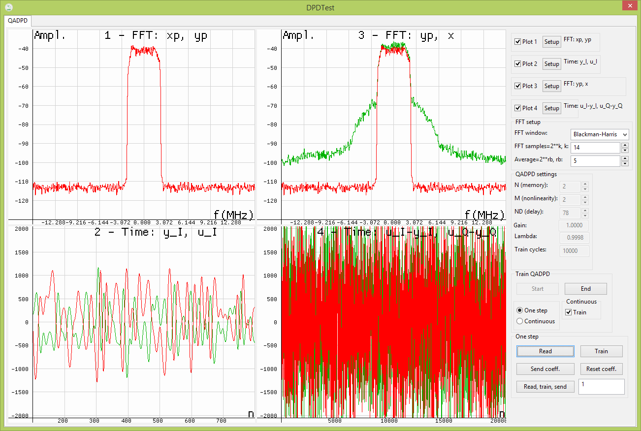
| 22:42, 3 June 2017 | Adpd-test-case-1-signals-before-training.png (file) |  |
50 KB | ADPD test case 1, signals before training. | 1 |
| 22:55, 3 June 2017 | Adpd-test-case-2-acpr-with-adpd.png (file) |  |
7 KB | ADPD test case 2, ACRP with ADPD. | 1 |
| 22:55, 3 June 2017 | Adpd-test-case-2-acpr-without-adpd.png (file) |  |
7 KB | ADPD test case 2, ACPR without ADPD. | 1 |
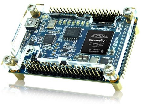
| 16:49, 13 July 2015 | DE0-Nano-1.jpg (file) |  |
74 KB | DE0-Nano FPGA Development System. | 1 |
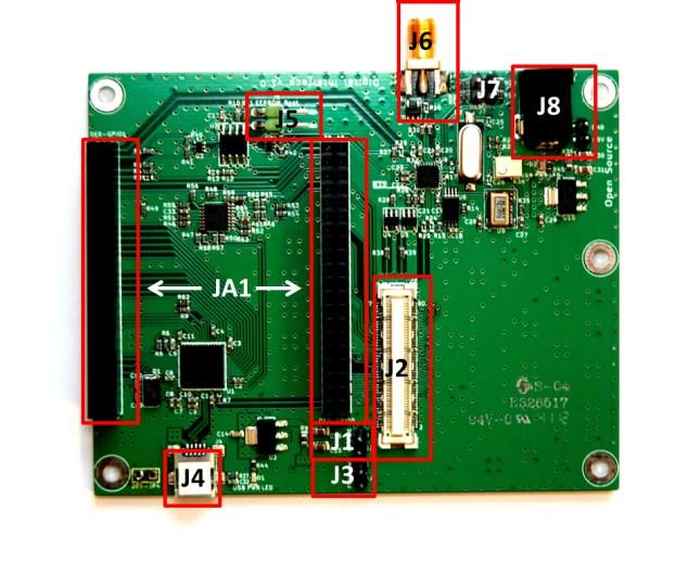
| 16:04, 16 July 2015 | DE0-Nano-Connections.jpg (file) |  |
54 KB | DE0-Nano Interface Board with connections labelled. | 1 |
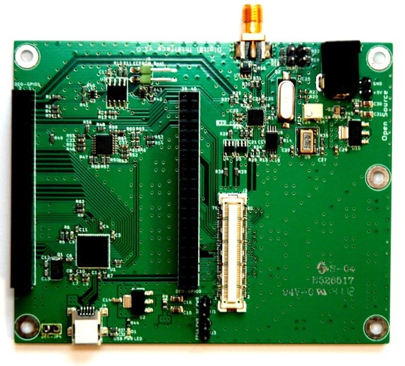
| 15:53, 13 July 2015 | DE0-Nano-Interface-Board-1.jpg (file) |  |
157 KB | The Digital Interface Board for connecting the DE0-Nano FPGA Development System to the Myriad-RF 1. | 1 |
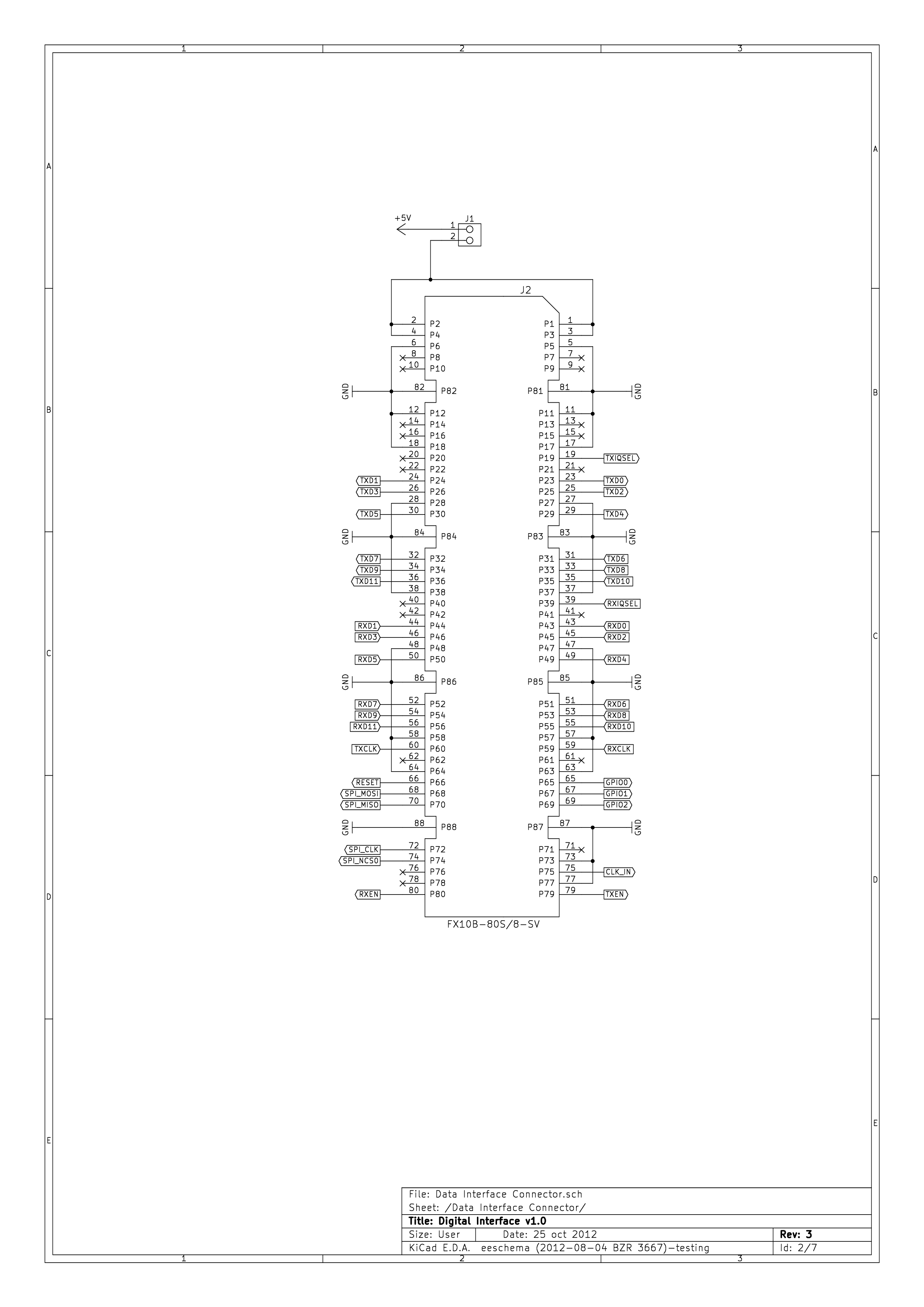
| 14:41, 16 July 2015 | DE0-Nano-Interface-Board-Schematics-1.png (file) |  |
144 KB | DE0-Nano Interface Board Schematic Sheet 1, Data Interface Connector. | 1 |
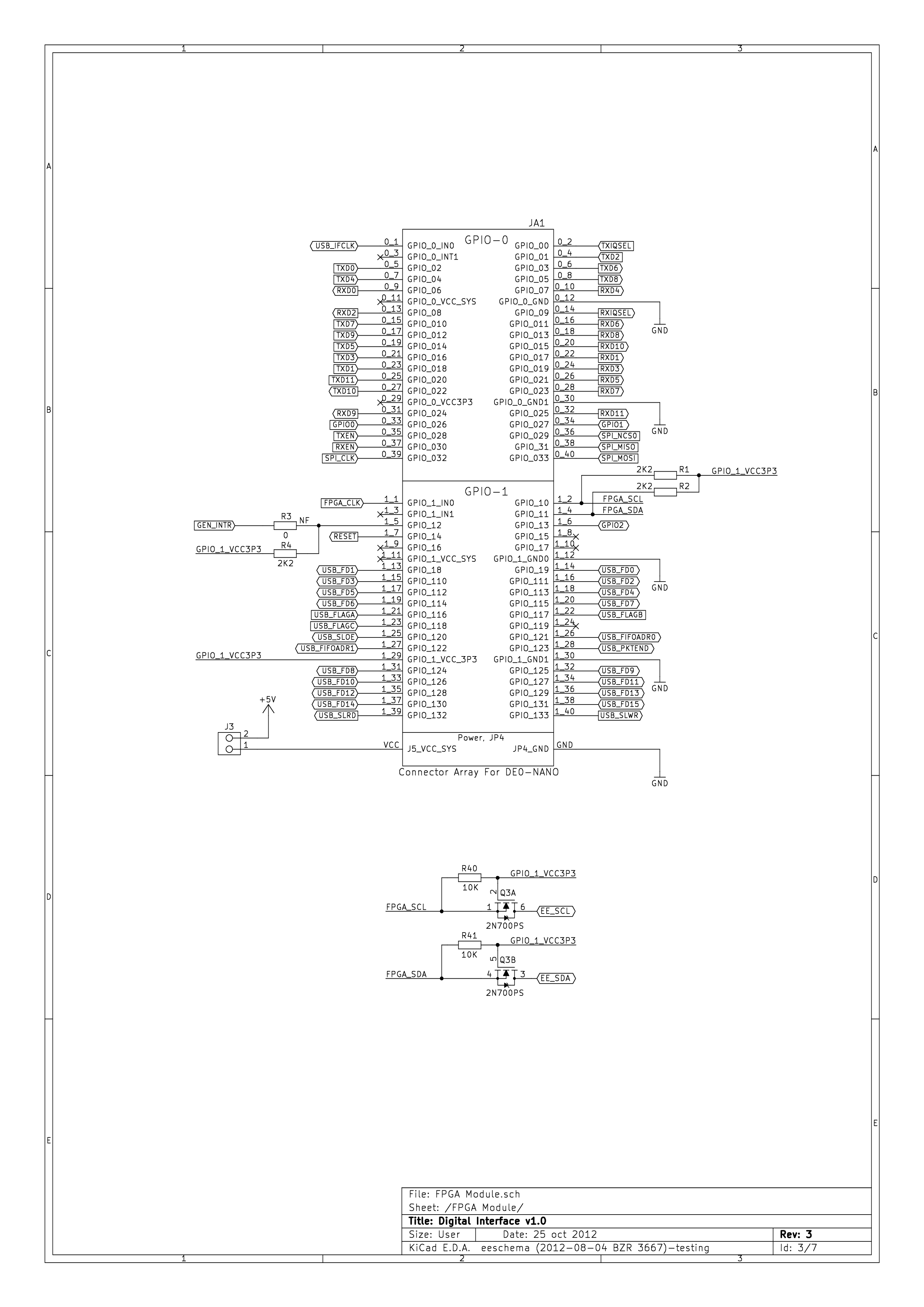
| 14:41, 16 July 2015 | DE0-Nano-Interface-Board-Schematics-2.png (file) |  |
222 KB | DE0-Nano Interface Board Schematic Sheet 2, FPGA Module. | 1 |
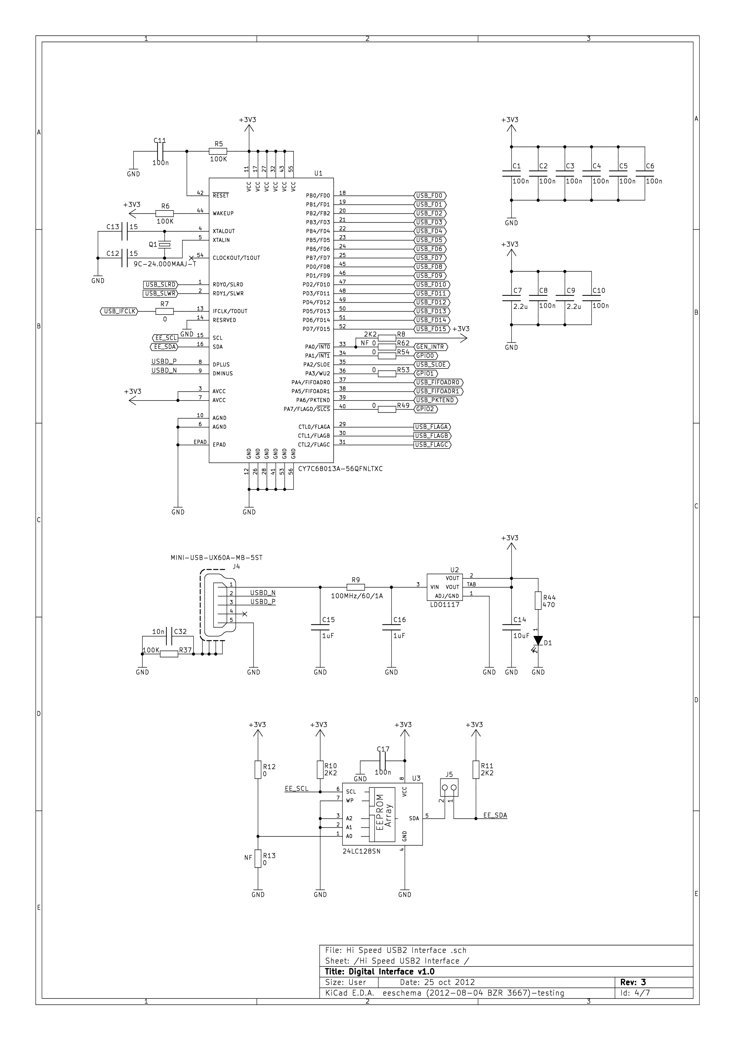
| 14:42, 16 July 2015 | DE0-Nano-Interface-Board-Schematics-3.png (file) |  |
194 KB | DE0-Nano Interface Board Schematic Sheet 3, Hi-Speed USB 2.0 Interface. | 1 |
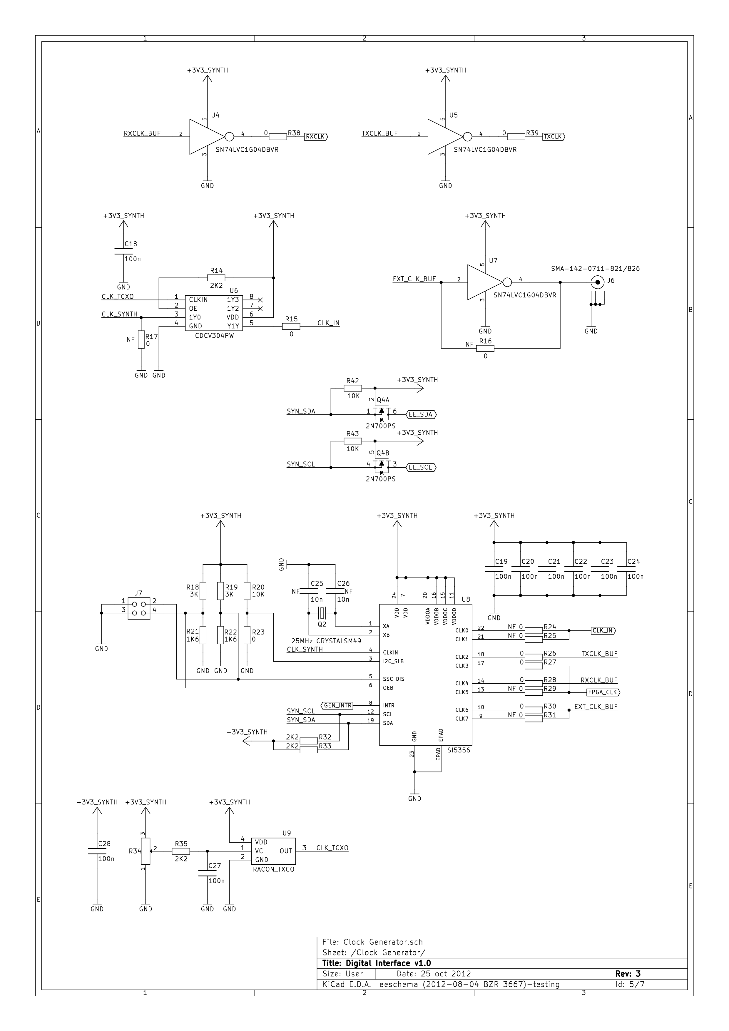
| 14:42, 16 July 2015 | DE0-Nano-Interface-Board-Schematics-4.png (file) |  |
171 KB | DE0-Nano Interface Board Schematic Sheet 4, Clock Generator. | 1 |
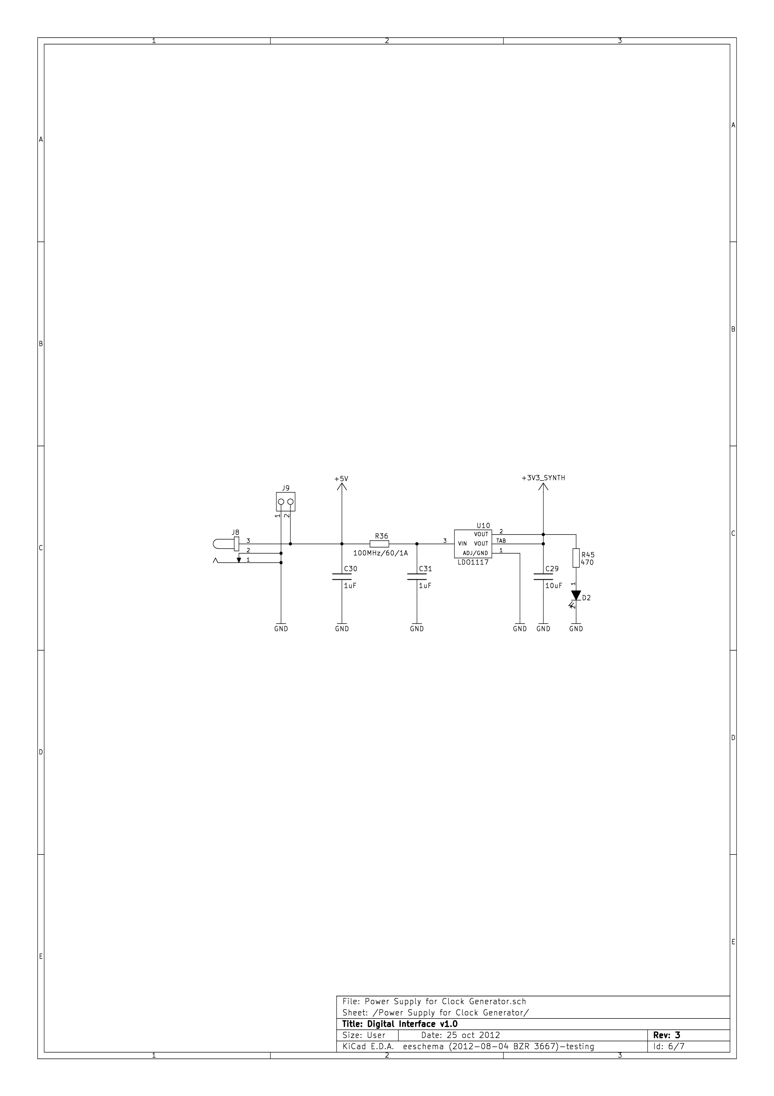
| 14:43, 16 July 2015 | DE0-Nano-Interface-Board-Schematics-5.png (file) |  |
65 KB | DE0-Nano Interface Board Schematic Sheet 5, Power Supply for Clock Generator. | 1 |
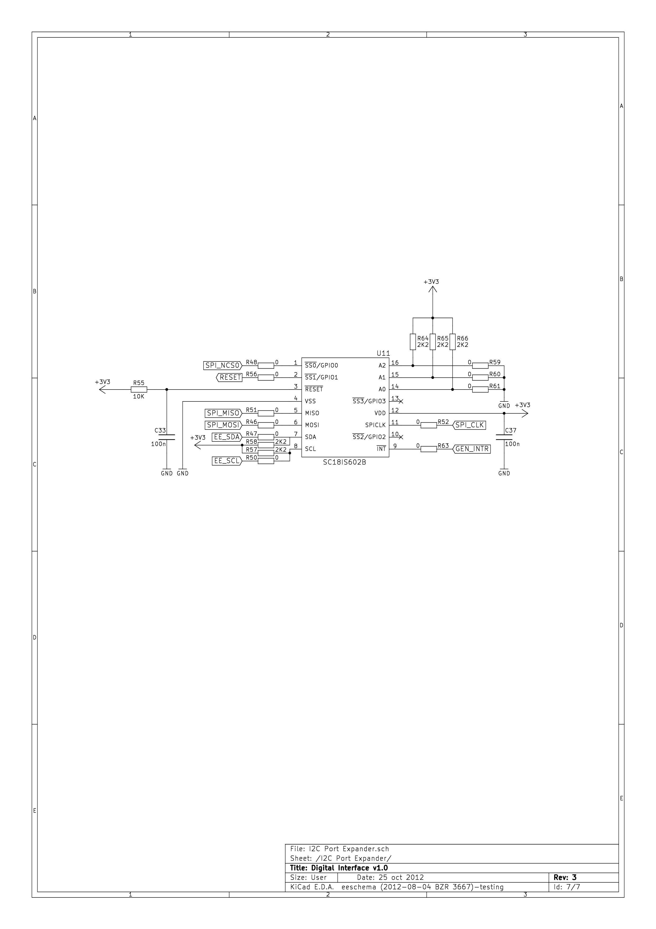
| 14:43, 16 July 2015 | DE0-Nano-Interface-Board-Schematics-6.png (file) |  |
88 KB | DE0-Nano Interface Board Schematic Sheet 6, I²C Port Expander. | 1 |
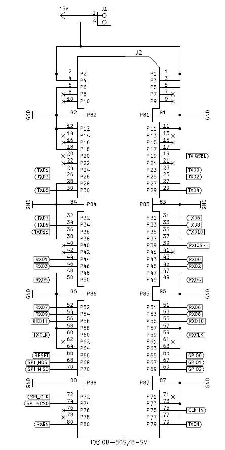
| 16:35, 16 July 2015 | DE0-Nano-J2.jpg (file) |  |
61 KB | DE0-Nano J2 connector pin-out. | 1 |
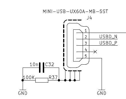
| 16:37, 16 July 2015 | DE0-Nano-J4.jpg (file) |  |
15 KB | DE0-Nano Interface Board J4, mini-USB connector. | 1 |
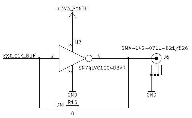
| 16:39, 16 July 2015 | DE0-Nano-J6.jpg (file) |  |
18 KB | DE0-Nano Interface Board J6 | 1 |
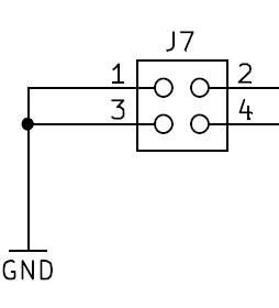
| 16:41, 16 July 2015 | DE0-Nano-J7.jpg (file) |  |
6 KB | DE0-Nano Interface Board J7. | 1 |
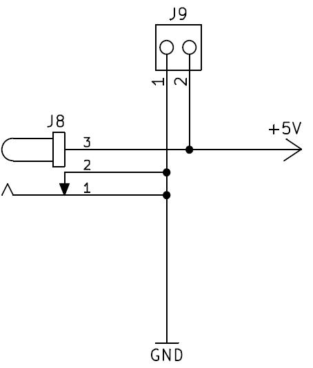
| 16:42, 16 July 2015 | DE0-Nano-J8-J9.jpg (file) |  |
12 KB | DE0-Nano Interface Board J8 and J9. | 1 |
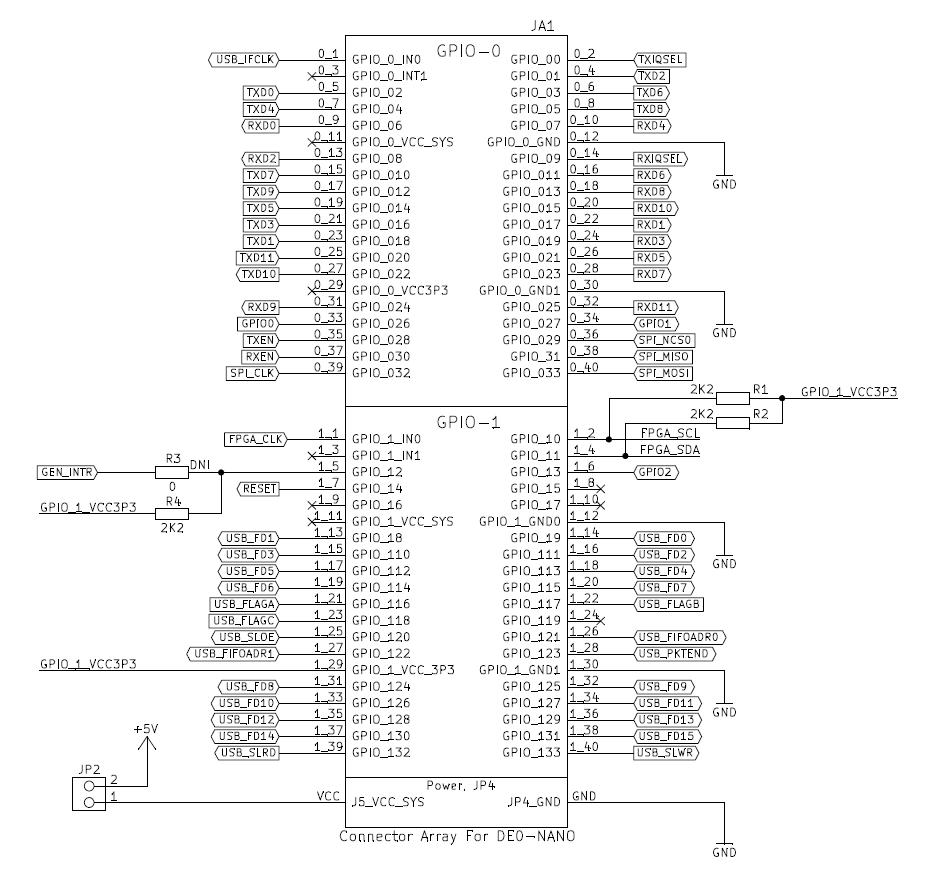
| 16:44, 16 July 2015 | DE0-Nano-JA1.jpg (file) |  |
127 KB | DE0-Nano Interface Board JA1. | 1 |
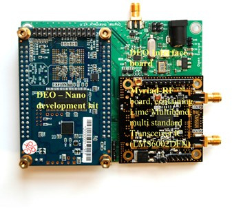
| 16:50, 13 July 2015 | DE0interfaceboard-Assembled-1.jpg (file) |  |
57 KB | DE0-Nano Interface Board, assembled with DE0-Nano and Myriad-RF1. | 1 |
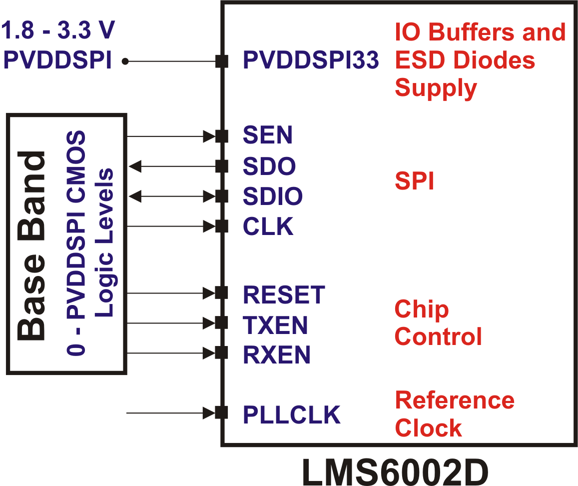
| 10:02, 1 October 2015 | LMS6002D-Baseband-Data-Interface.png (file) |  |
121 KB | Higher-resolution version. | 2 |
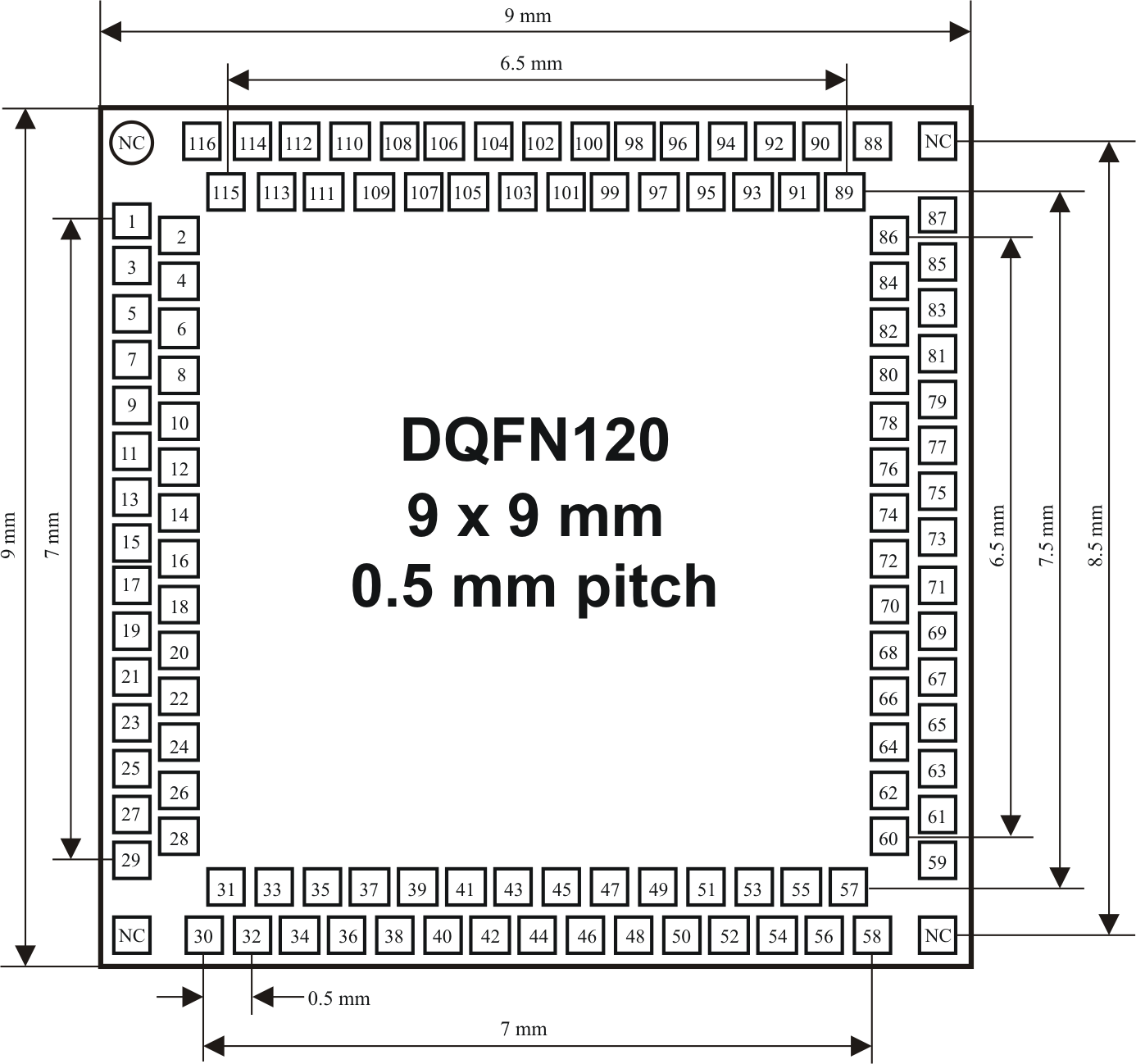
| 10:05, 1 October 2015 | LMS6002D-DQFN120-Package-Top-View.png (file) |  |
153 KB | Higher-resolution version. | 2 |
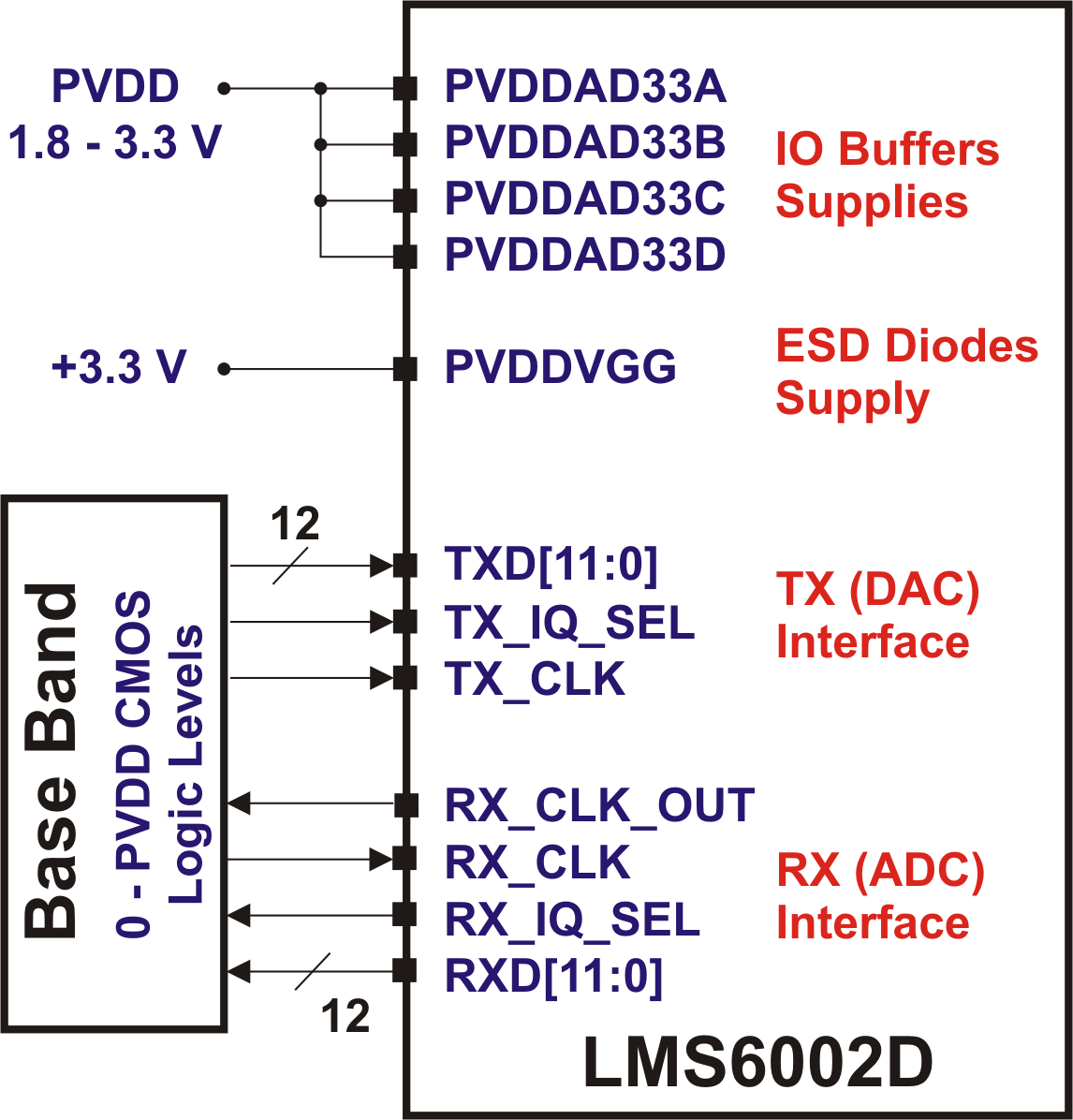
| 10:04, 1 October 2015 | LMS6002D-Digital-IQ-Interface-Supplies.png (file) |  |
155 KB | Higher-resolution version. | 2 |
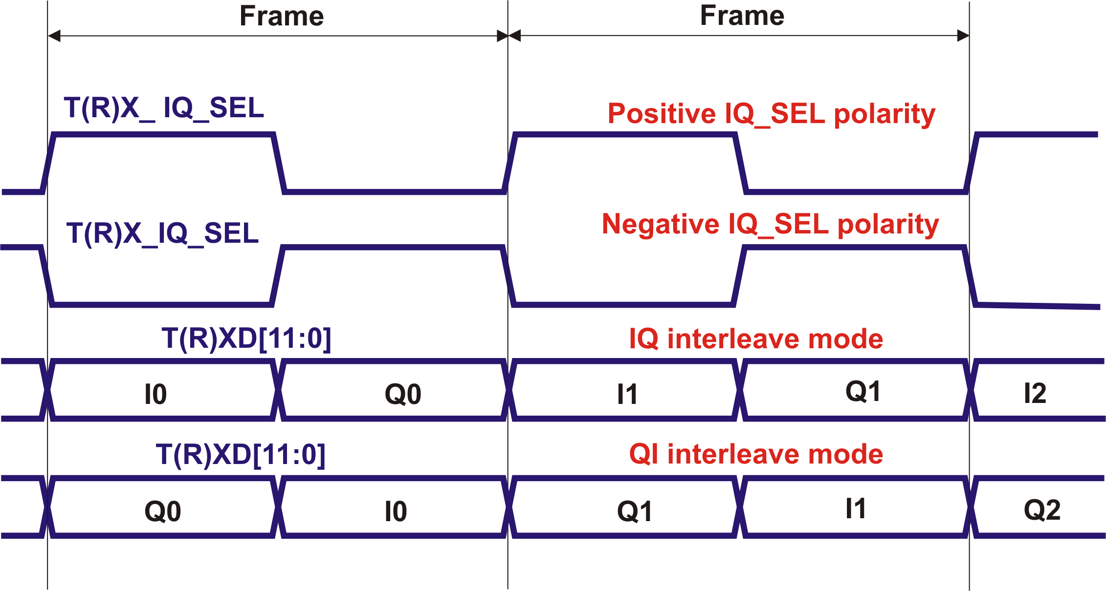
| 10:02, 1 October 2015 | LMS6002D-Frame-Sync-Polarity-Interleave-Modes.png (file) |  |
166 KB | Higher-resolution version. | 2 |
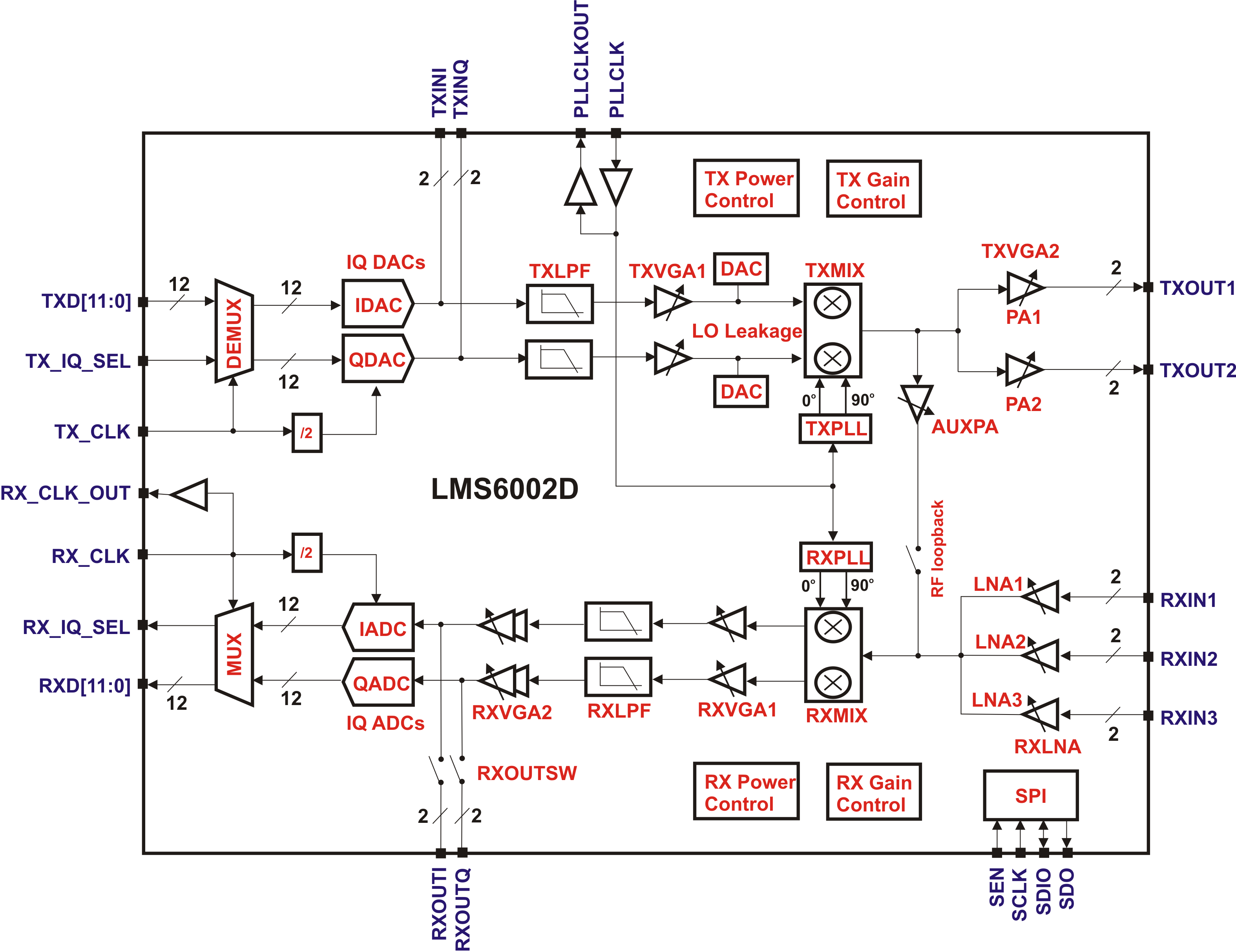
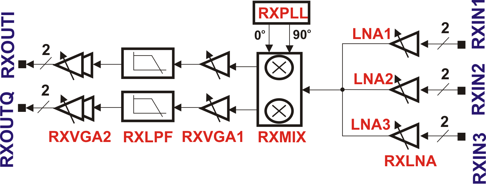
| 09:59, 1 October 2015 | LMS6002D-Functional-Block-Diagram.png (file) |  |
475 KB | Higher-resolution version. | 2 |
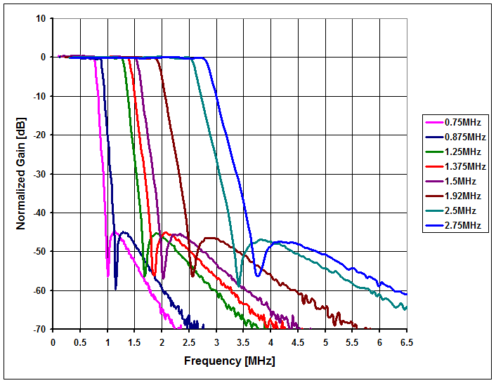
| 10:01, 1 October 2015 | LMS6002D-LPF-Amplitude-Response-1.png (file) |  |
34 KB | Higher-resolution version. | 2 |
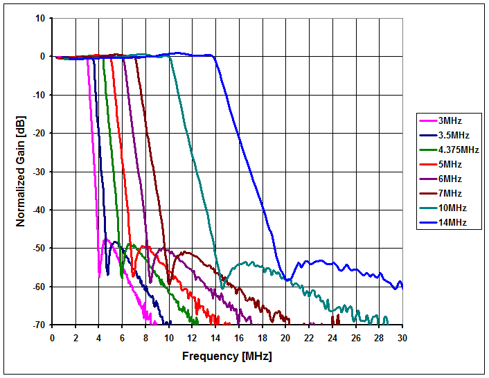
| 10:01, 1 October 2015 | LMS6002D-LPF-Amplitude-Response-2.png (file) |  |
34 KB | Higher-resolution version. | 2 |
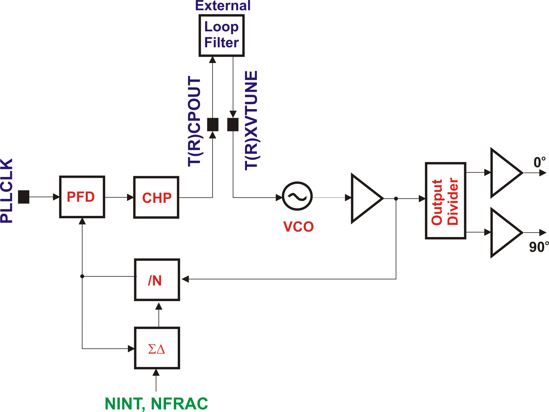
| 10:00, 1 October 2015 | LMS6002D-PLL-Architecture.png (file) |  |
106 KB | Higher-resolution version. | 2 |
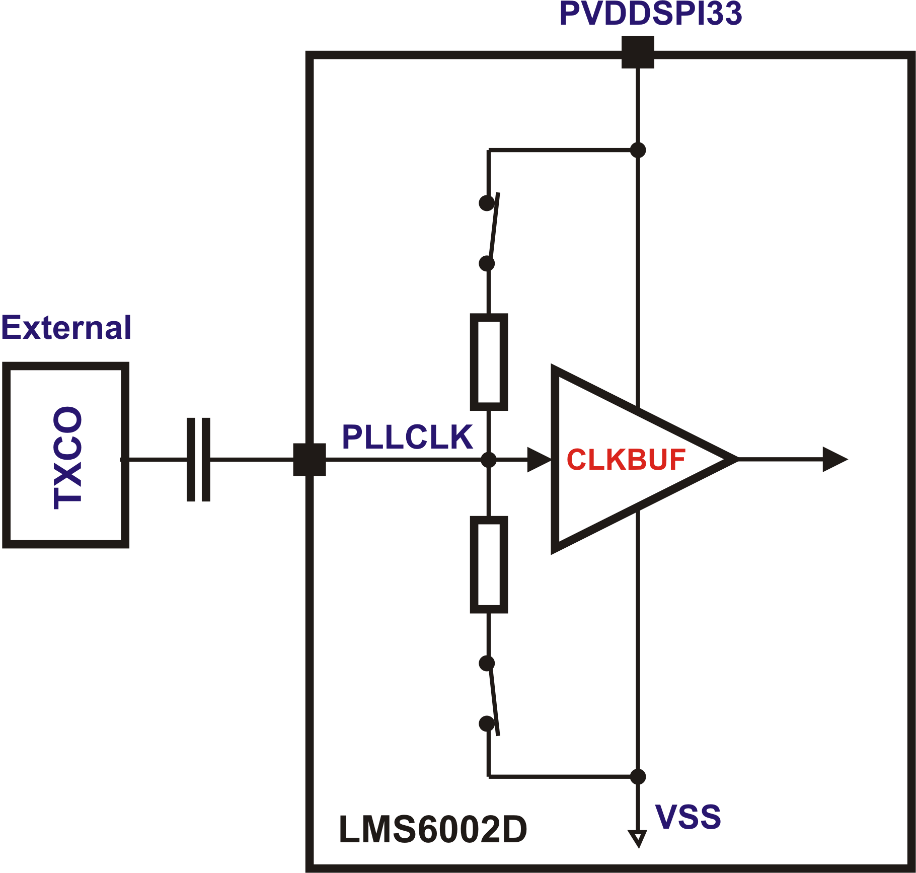
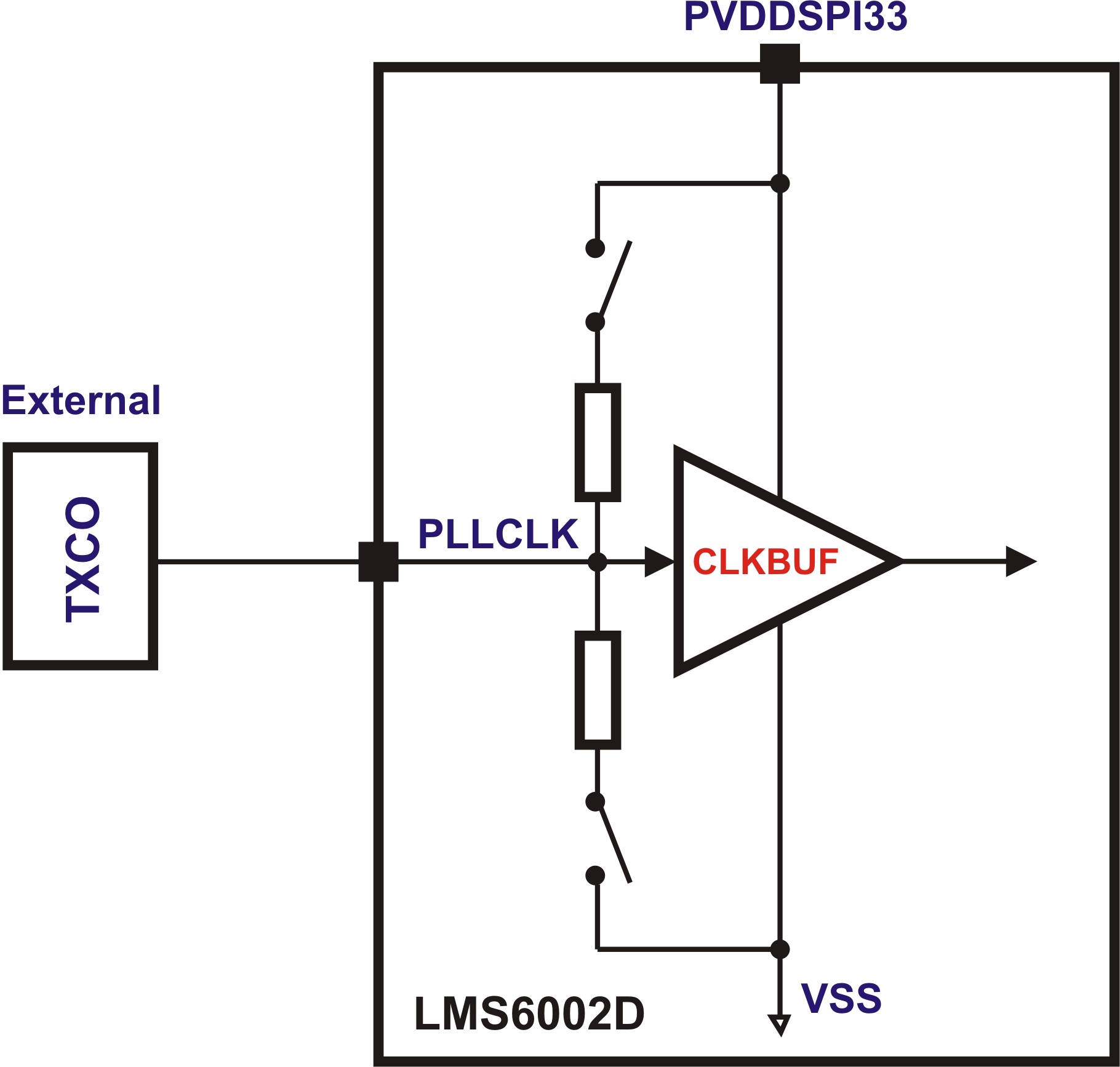
| 10:01, 1 October 2015 | LMS6002D-PLL-Reference-Clock-Input-Buffer-AC-Coupled.png (file) |  |
95 KB | Higher-resolution version. | 2 |
| 10:00, 1 October 2015 | LMS6002D-PLL-Reference-Clock-Input-Buffer-DC-Coupled.png (file) |  |
95 KB | Higher-resolution version. | 2 |
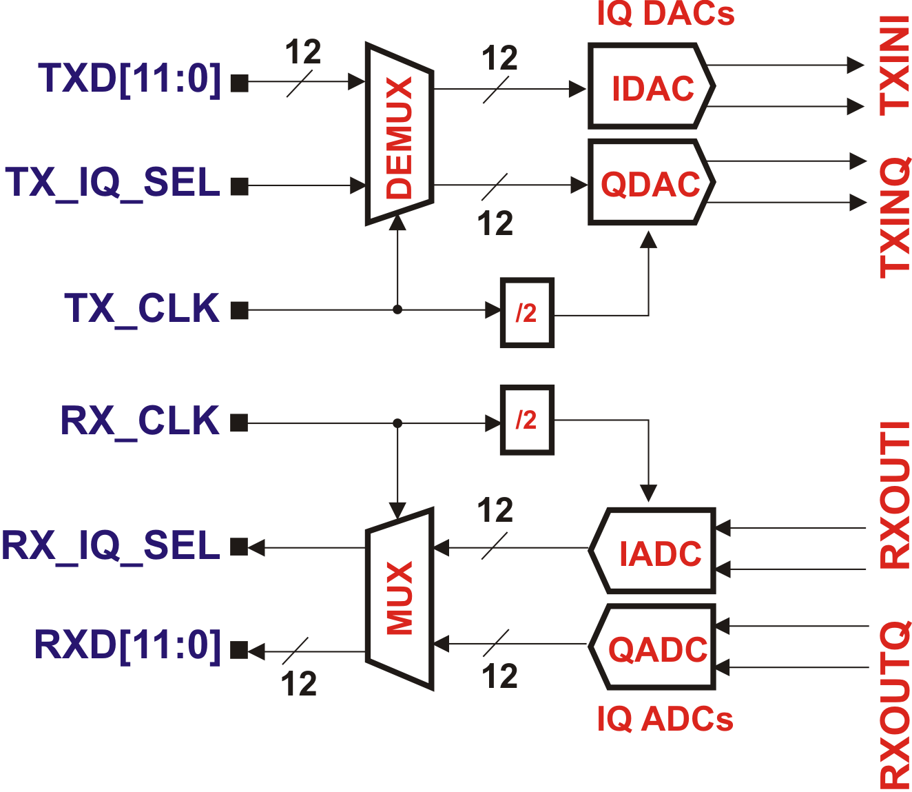
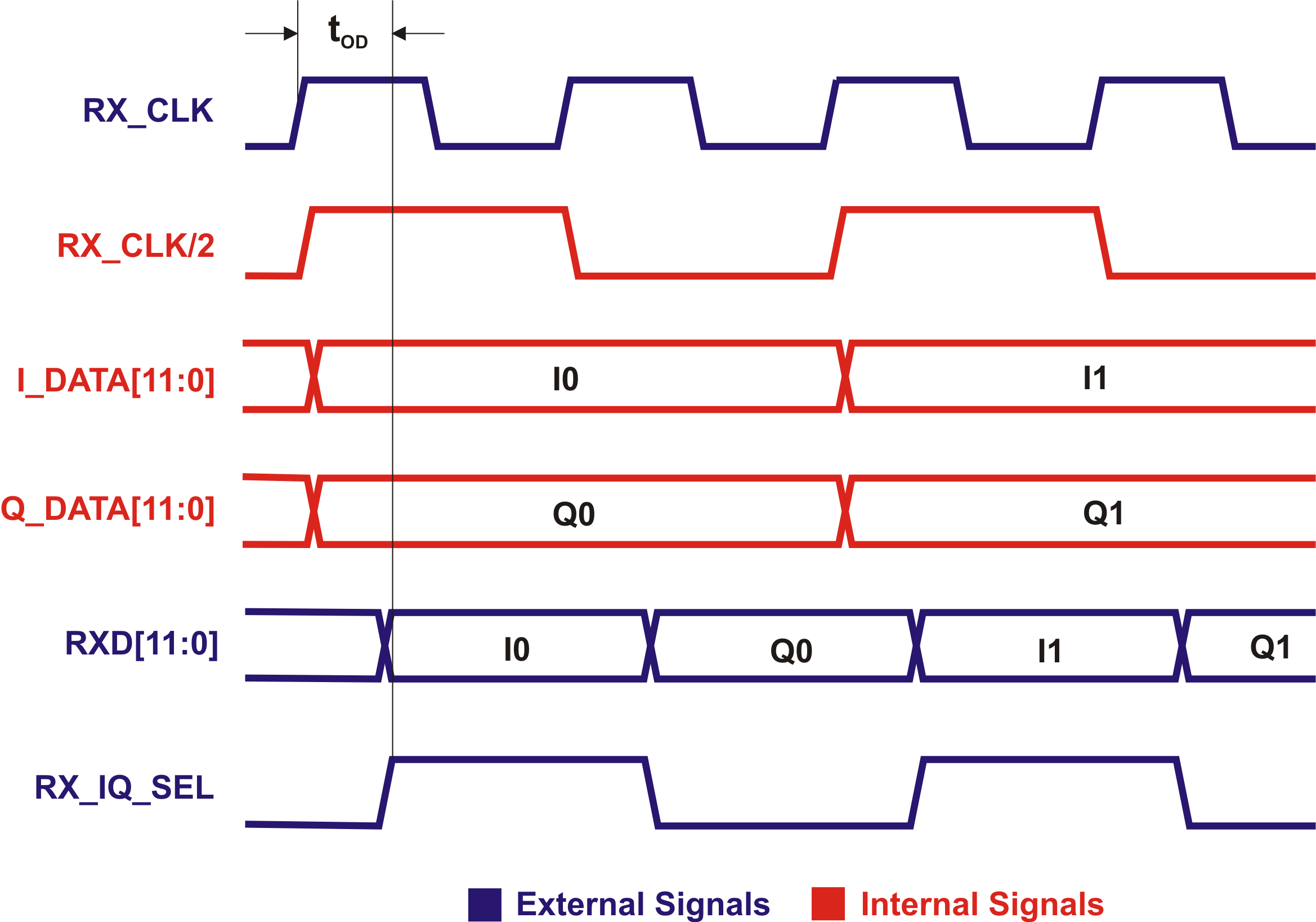
| 10:04, 1 October 2015 | LMS6002D-RX-Data-Interface-Signals.png (file) |  |
151 KB | Higher-resolution version. | 2 |
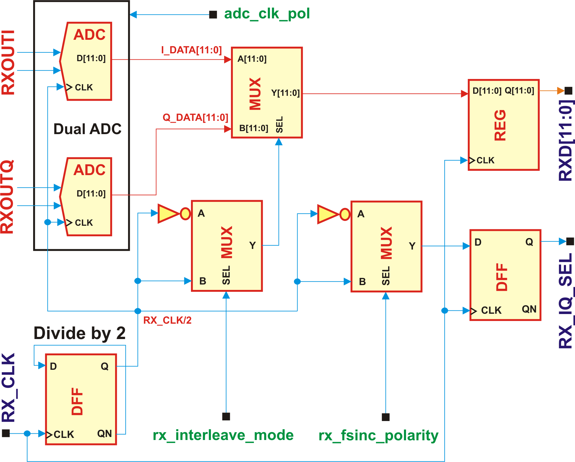
| 10:03, 1 October 2015 | LMS6002D-RX-Data-Interface.png (file) |  |
192 KB | Higher-resolution version. | 2 |
| 09:59, 1 October 2015 | LMS6002D-RX-Gain-Control-Architecture.png (file) |  |
109 KB | Higher-resolution version. | 2 |
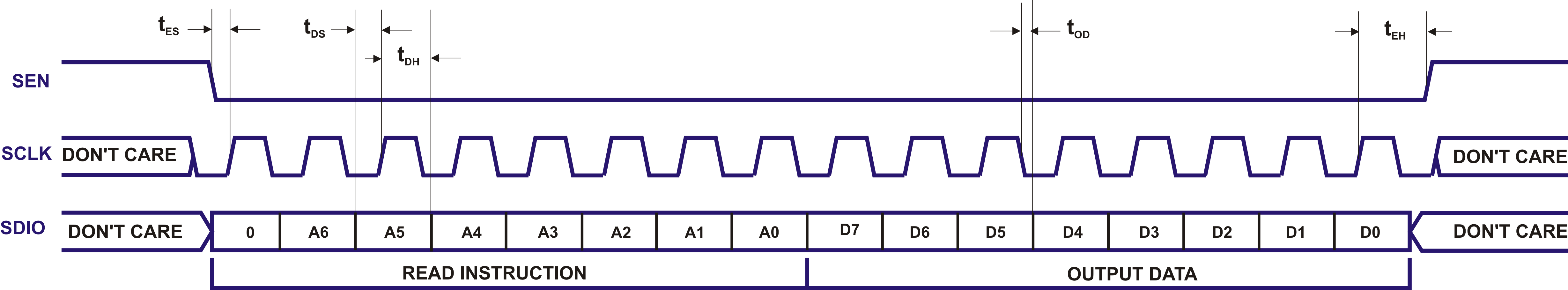
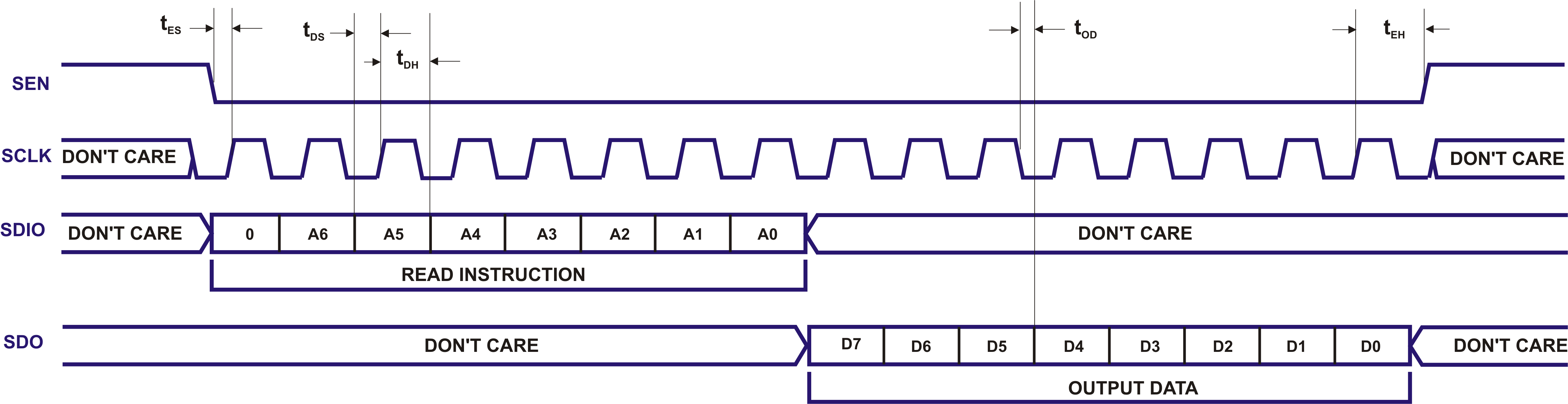
| 09:57, 1 October 2015 | LMS6002D-SPI-Read-Cycle-3-Wire.png (file) | 200 KB | Higher-resolution version. | 2 | |
| 09:56, 1 October 2015 | LMS6002D-SPI-Read-Cycle-4-Wire.png (file) | 230 KB | Higher-resolution version. | 4 | |
| 10:05, 1 October 2015 | LMS6002D-SPI-Supplies.png (file) |  |
115 KB | Higher-resolution version. | 2 |
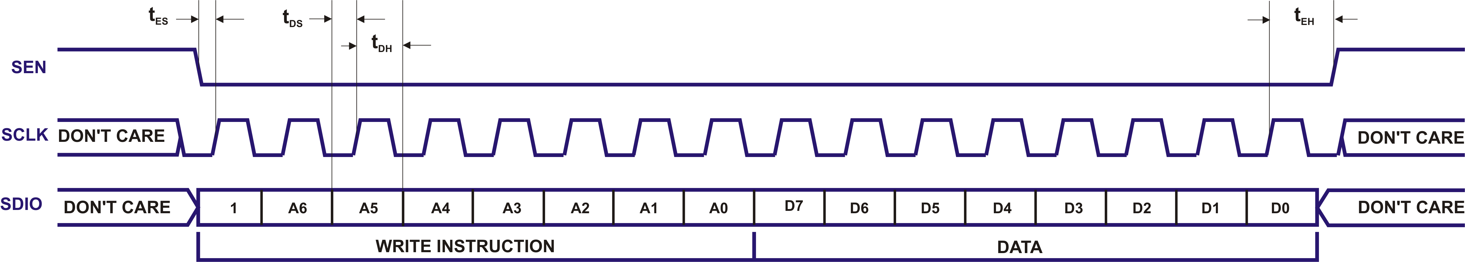
| 09:54, 1 October 2015 | LMS6002D-SPI-Write-Cycle.png (file) | 189 KB | Higher-resolution version. | 2 | |
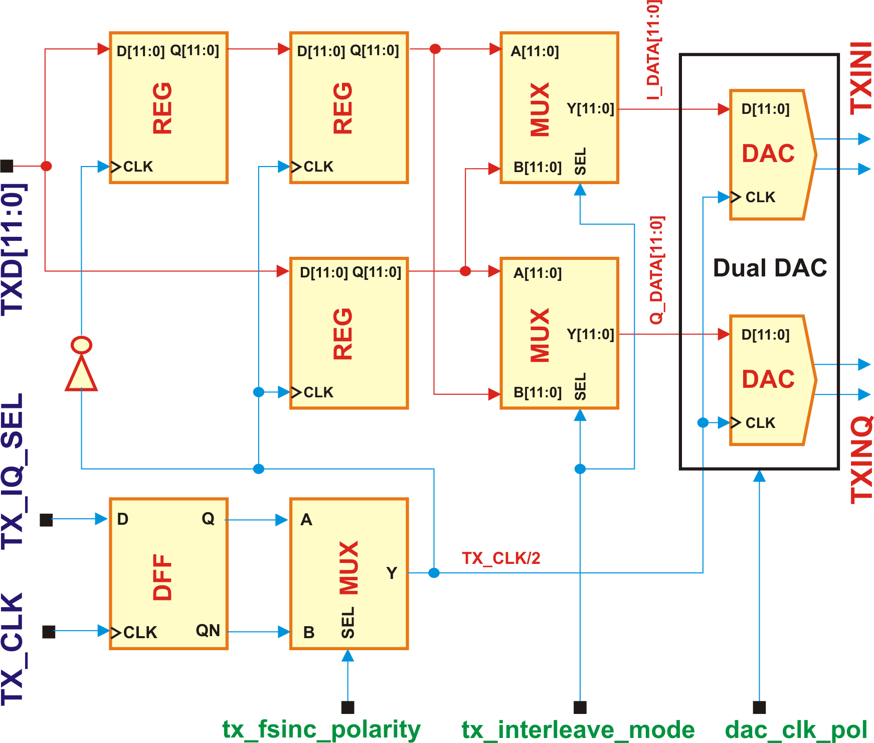
| 10:03, 1 October 2015 | LMS6002D-TX-Data-Interface.png (file) |  |
190 KB | Higher-resolution version. | 2 |
| 09:59, 1 October 2015 | LMS6002D-TX-Gain-Control-Architecture.png (file) |  |
91 KB | Higher-resolution version. | 2 |
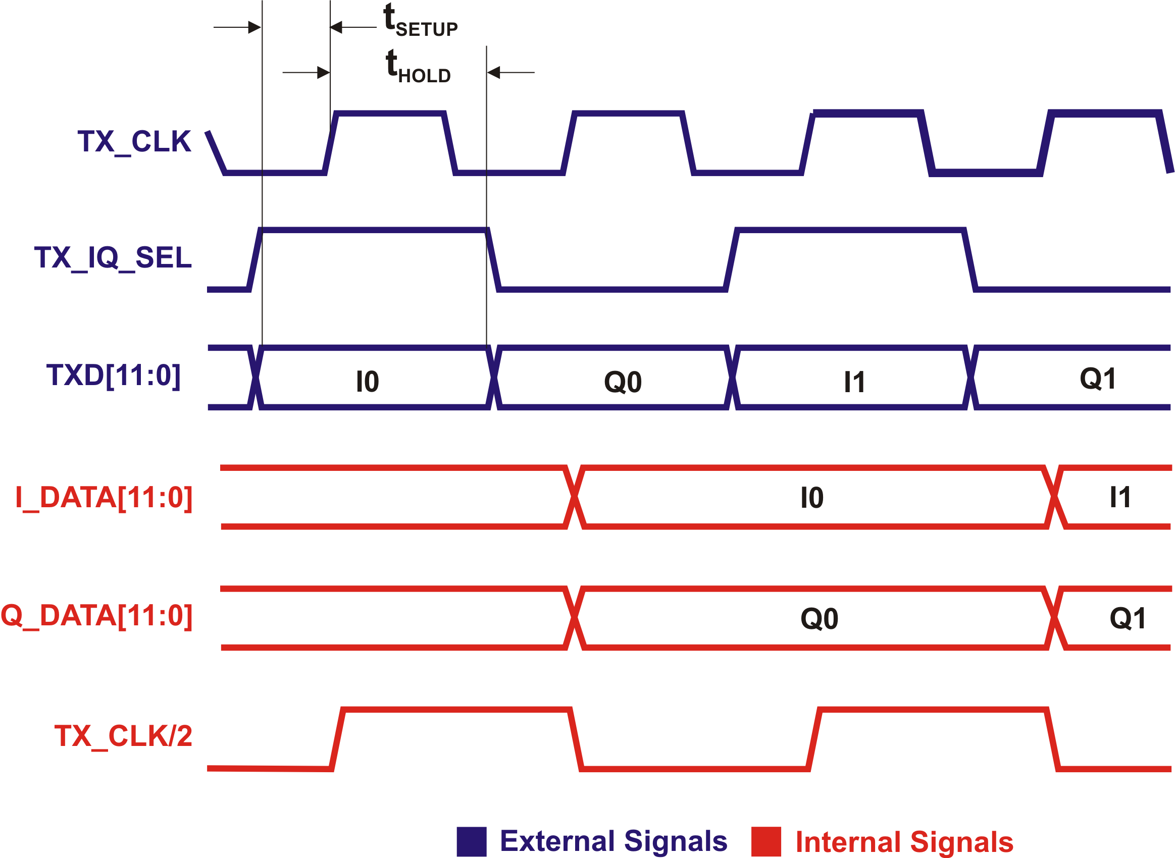
| 10:03, 1 October 2015 | LMS6002D-TX-IQ-Interface-Signals.png (file) |  |
150 KB | Higher-resolution version. | 2 |
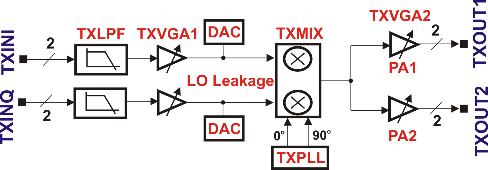
| 10:05, 1 October 2015 | LMS6002D-Typical-Application-Circuit-RF-Part.png (file) |  |
41 KB | Higher-resolution version. | 2 |
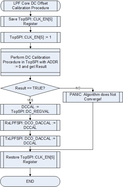
| 14:51, 6 October 2015 | LMS6002Dr2-DC-Offset-Calibration-LPF-Tuning-Module.png (file) |  |
19 KB | Higher resolution version. | 2 |
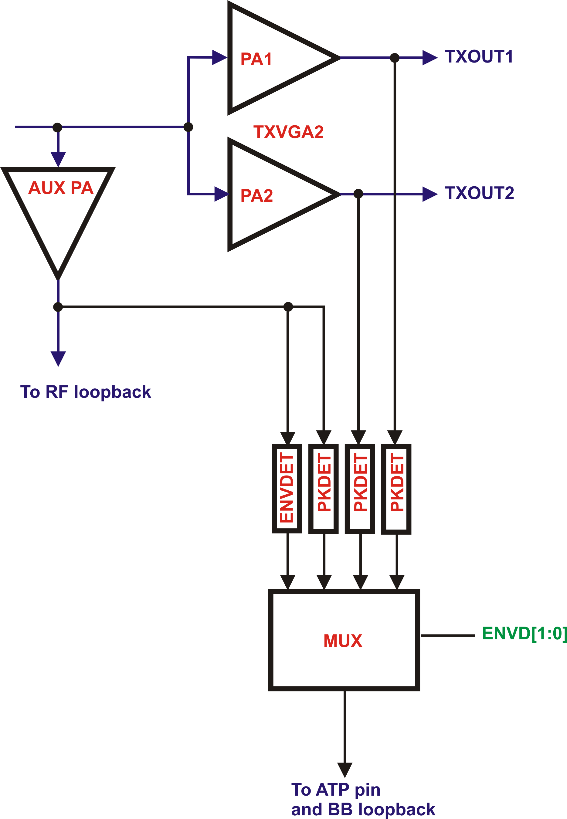
| 14:36, 6 October 2015 | LMS6002Dr2-Envelop-Pick-Detector.png (file) |  |
146 KB | Higher resolution copy. | 2 |