File list
Jump to navigation
Jump to search
This special page shows all uploaded files.
| Date | Name | Thumbnail | Size | User | Description | Versions |
|---|---|---|---|---|---|---|
| 21:25, 28 May 2015 | Clocktamer lvds at usrp.png (file) |  |
37 KB | AndrewBack | 1 | |
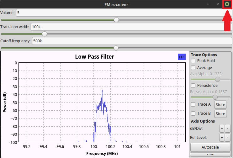
| 10:20, 24 April 2018 | Close WX GUI Button GnuRadio.png (file) |  |
61 KB | ZydrunasTamosevicius | 1 | |
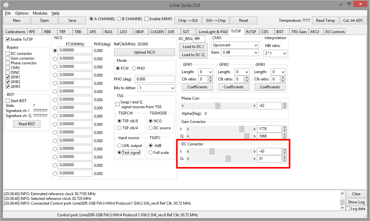
| 10:25, 29 August 2017 | DC offset block control.png (file) |  |
242 KB | ZydrunasTamosevicius | 1 | |
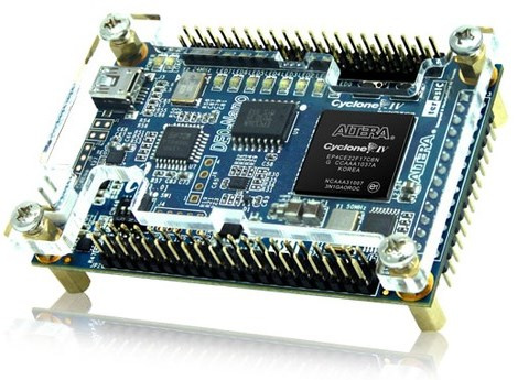
| 16:49, 13 July 2015 | DE0-Nano-1.jpg (file) |  |
74 KB | Ghalfacree | DE0-Nano FPGA Development System. | 1 |
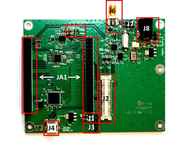
| 16:04, 16 July 2015 | DE0-Nano-Connections.jpg (file) |  |
54 KB | Ghalfacree | DE0-Nano Interface Board with connections labelled. | 1 |
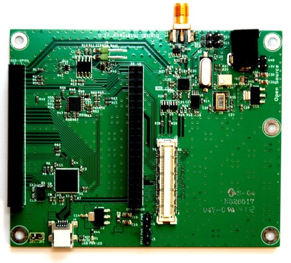
| 15:53, 13 July 2015 | DE0-Nano-Interface-Board-1.jpg (file) |  |
157 KB | Ghalfacree | The Digital Interface Board for connecting the DE0-Nano FPGA Development System to the Myriad-RF 1. | 1 |
| 14:41, 16 July 2015 | DE0-Nano-Interface-Board-Schematics-1.png (file) |  |
144 KB | Ghalfacree | DE0-Nano Interface Board Schematic Sheet 1, Data Interface Connector. | 1 |
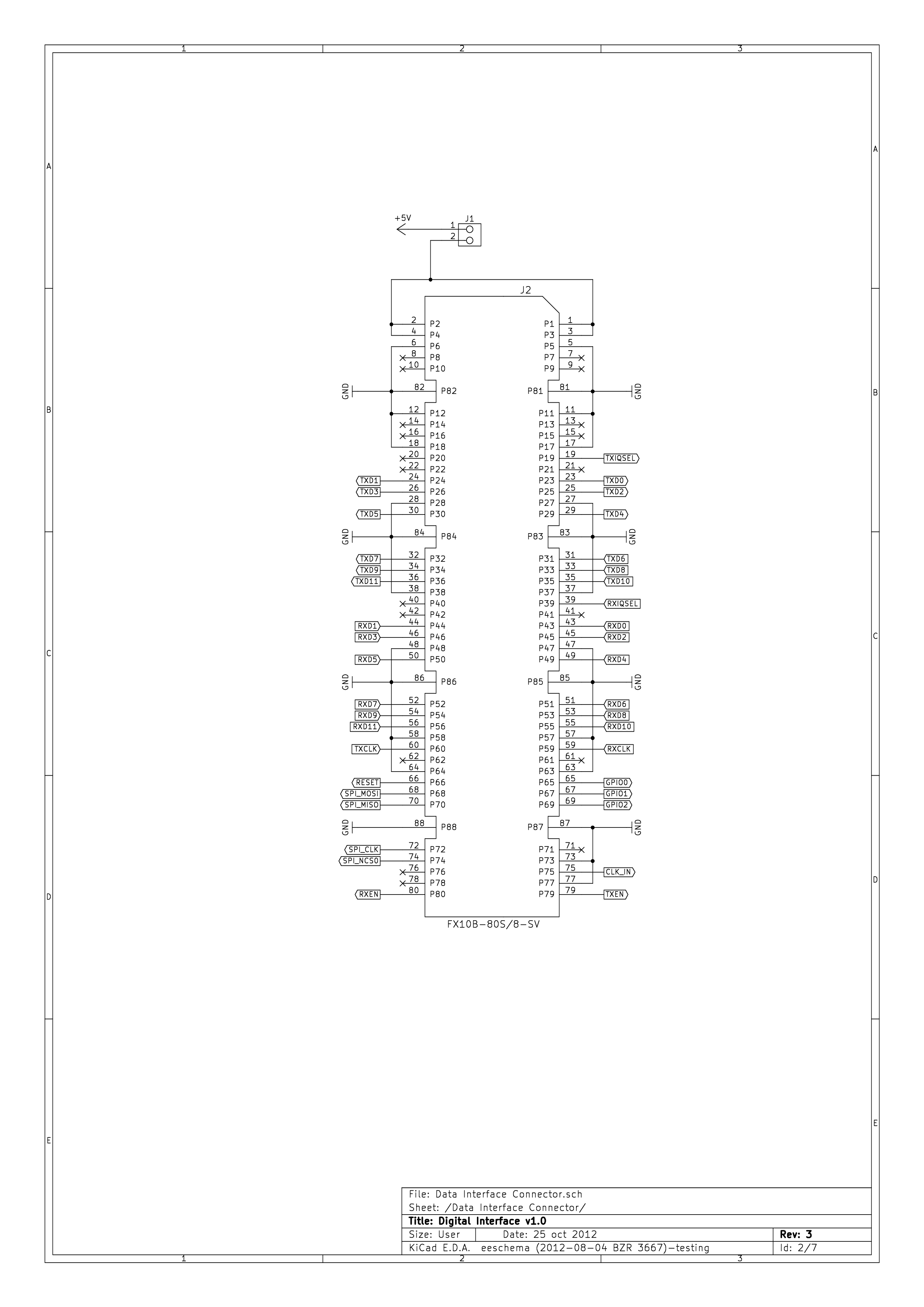
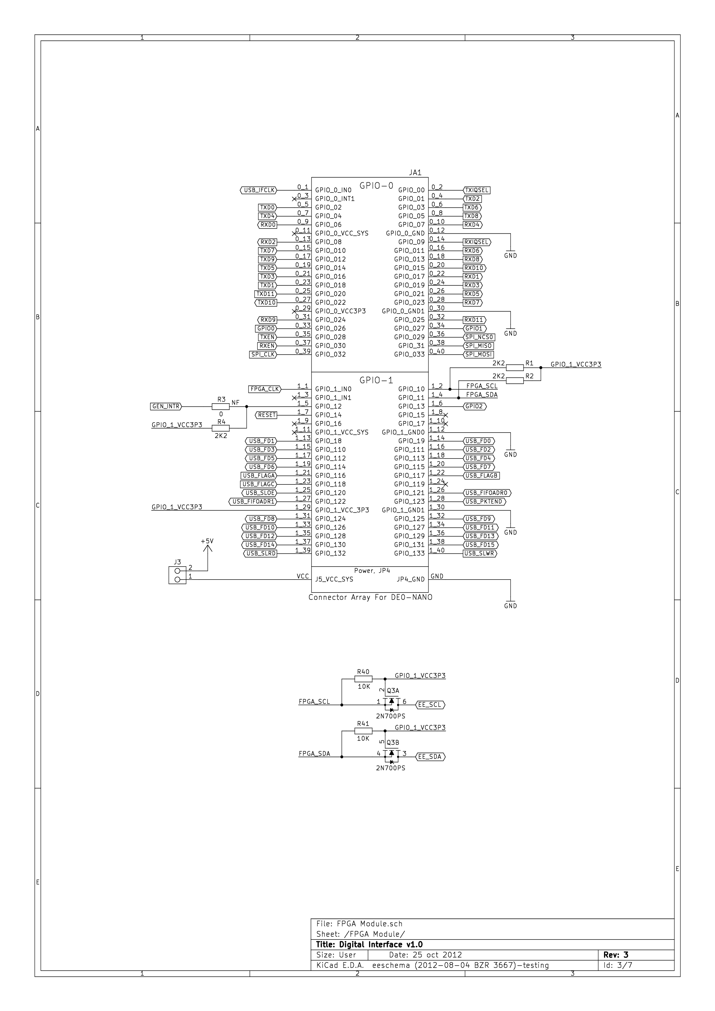
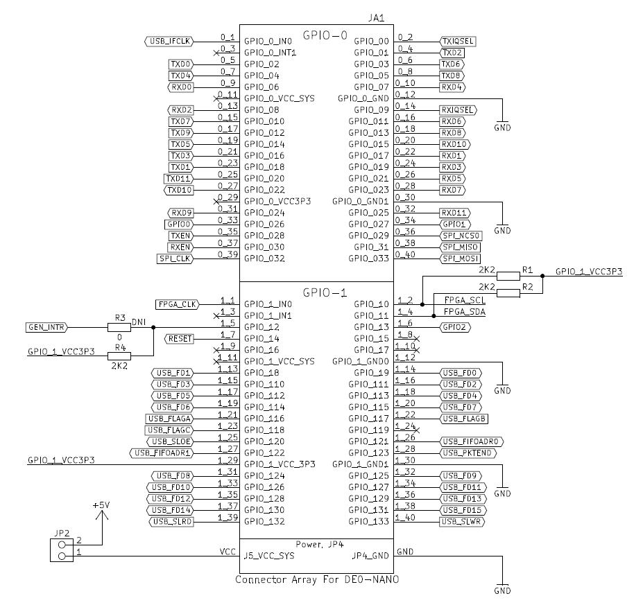
| 14:41, 16 July 2015 | DE0-Nano-Interface-Board-Schematics-2.png (file) |  |
222 KB | Ghalfacree | DE0-Nano Interface Board Schematic Sheet 2, FPGA Module. | 1 |
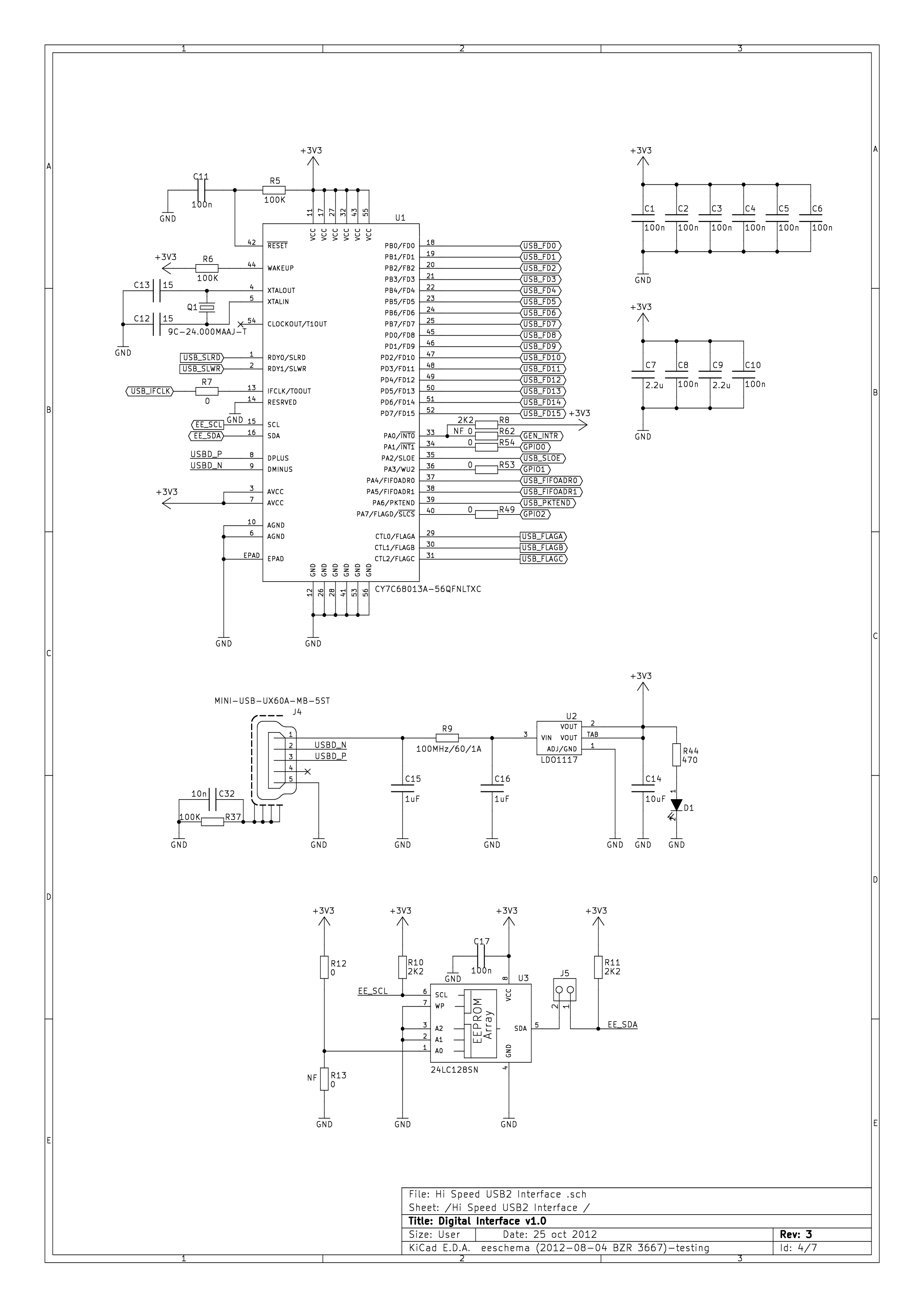
| 14:42, 16 July 2015 | DE0-Nano-Interface-Board-Schematics-3.png (file) |  |
194 KB | Ghalfacree | DE0-Nano Interface Board Schematic Sheet 3, Hi-Speed USB 2.0 Interface. | 1 |
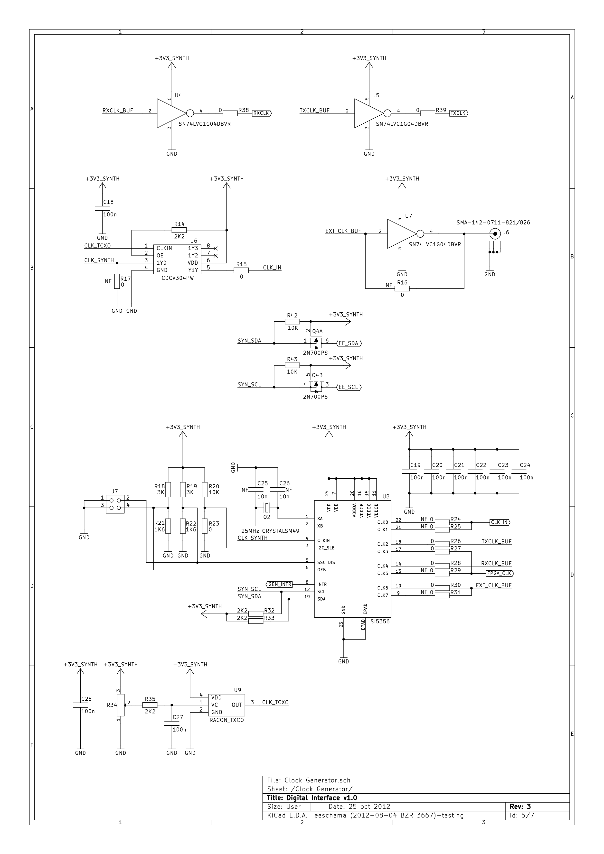
| 14:42, 16 July 2015 | DE0-Nano-Interface-Board-Schematics-4.png (file) |  |
171 KB | Ghalfacree | DE0-Nano Interface Board Schematic Sheet 4, Clock Generator. | 1 |
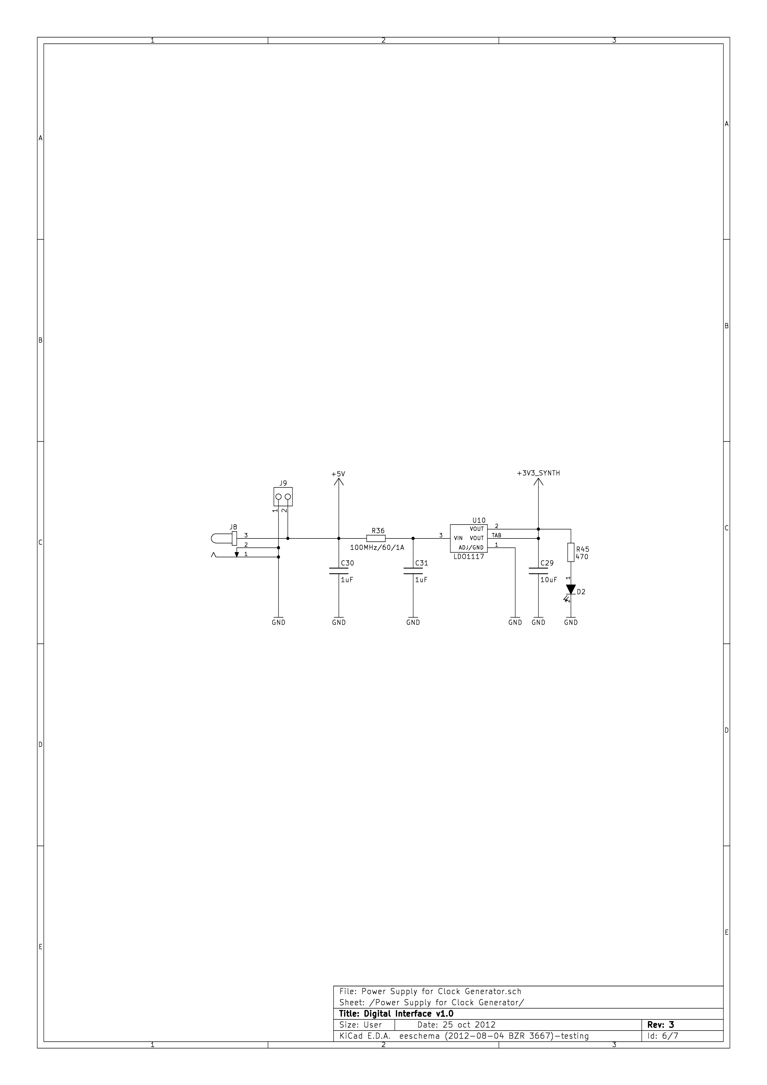
| 14:43, 16 July 2015 | DE0-Nano-Interface-Board-Schematics-5.png (file) |  |
65 KB | Ghalfacree | DE0-Nano Interface Board Schematic Sheet 5, Power Supply for Clock Generator. | 1 |
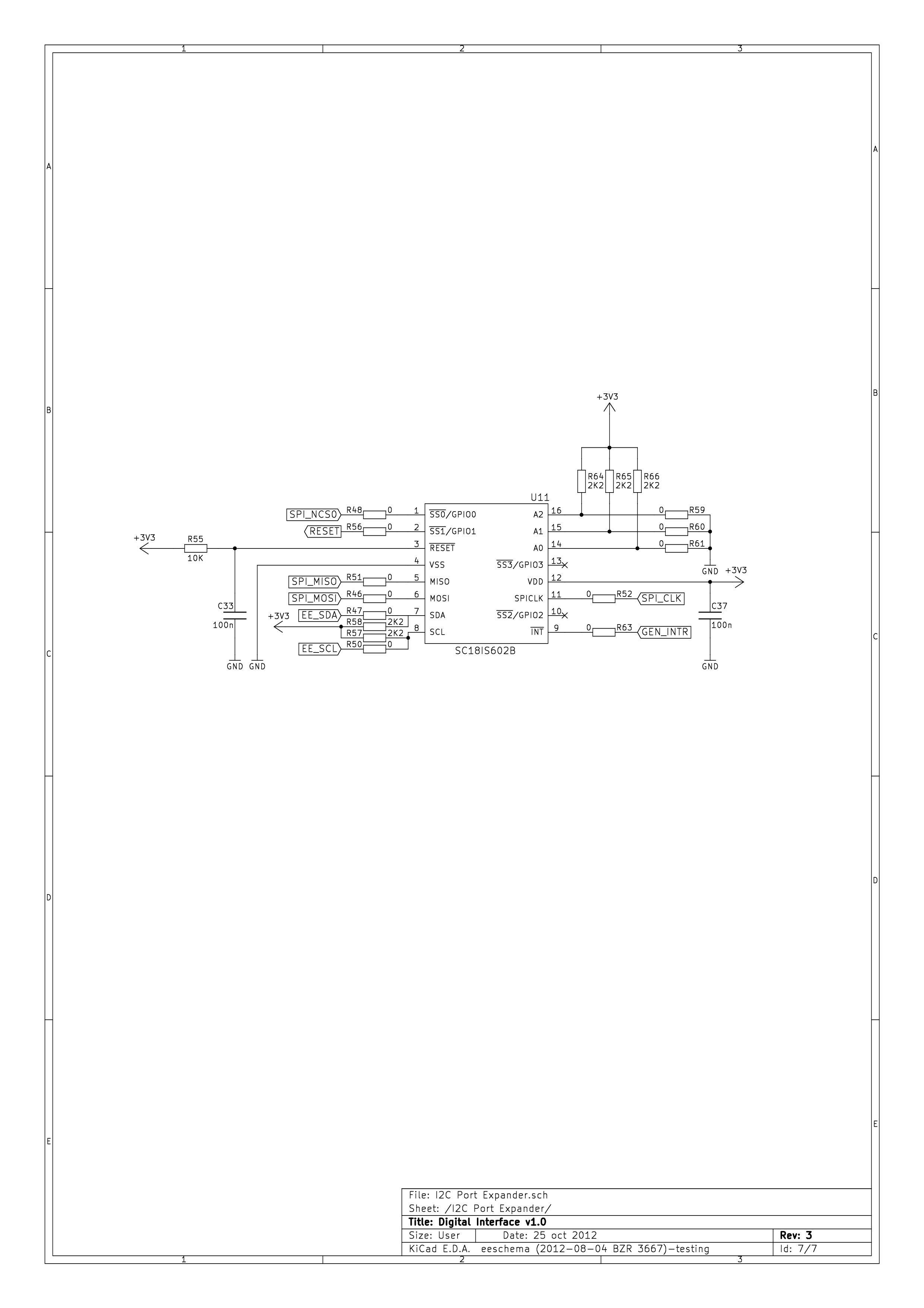
| 14:43, 16 July 2015 | DE0-Nano-Interface-Board-Schematics-6.png (file) |  |
88 KB | Ghalfacree | DE0-Nano Interface Board Schematic Sheet 6, I²C Port Expander. | 1 |
| 16:35, 16 July 2015 | DE0-Nano-J2.jpg (file) |  |
61 KB | Ghalfacree | DE0-Nano J2 connector pin-out. | 1 |
| 16:37, 16 July 2015 | DE0-Nano-J4.jpg (file) |  |
15 KB | Ghalfacree | DE0-Nano Interface Board J4, mini-USB connector. | 1 |
| 16:39, 16 July 2015 | DE0-Nano-J6.jpg (file) |  |
18 KB | Ghalfacree | DE0-Nano Interface Board J6 | 1 |
| 16:41, 16 July 2015 | DE0-Nano-J7.jpg (file) |  |
6 KB | Ghalfacree | DE0-Nano Interface Board J7. | 1 |
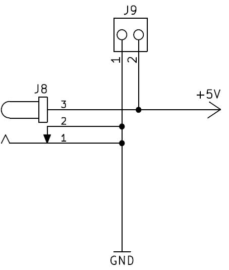
| 16:42, 16 July 2015 | DE0-Nano-J8-J9.jpg (file) |  |
12 KB | Ghalfacree | DE0-Nano Interface Board J8 and J9. | 1 |
| 16:44, 16 July 2015 | DE0-Nano-JA1.jpg (file) |  |
127 KB | Ghalfacree | DE0-Nano Interface Board JA1. | 1 |
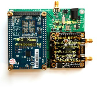
| 16:50, 13 July 2015 | DE0interfaceboard-Assembled-1.jpg (file) |  |
57 KB | Ghalfacree | DE0-Nano Interface Board, assembled with DE0-Nano and Myriad-RF1. | 1 |
| 16:10, 8 February 2019 | DVB-T transmitter example.png (file) | 121 KB | RicardasGarmus | 2 | ||
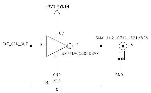
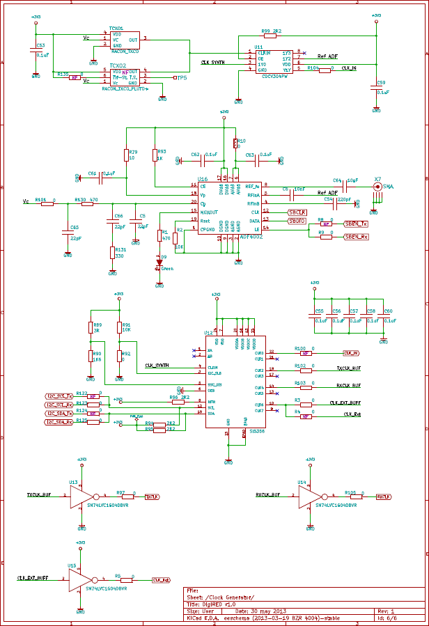
| 13:42, 15 September 2015 | Digired-clock-generator.png (file) |  |
56 KB | BogdanVacaliuc | page 5 of Digired schematic - transmit side cropped | 1 |
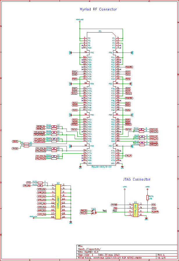
| 13:40, 15 September 2015 | Digired-connectors.png (file) |  |
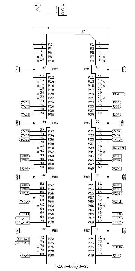
62 KB | BogdanVacaliuc | page 1 of Digired schematic - transmit side cropped | 1 |
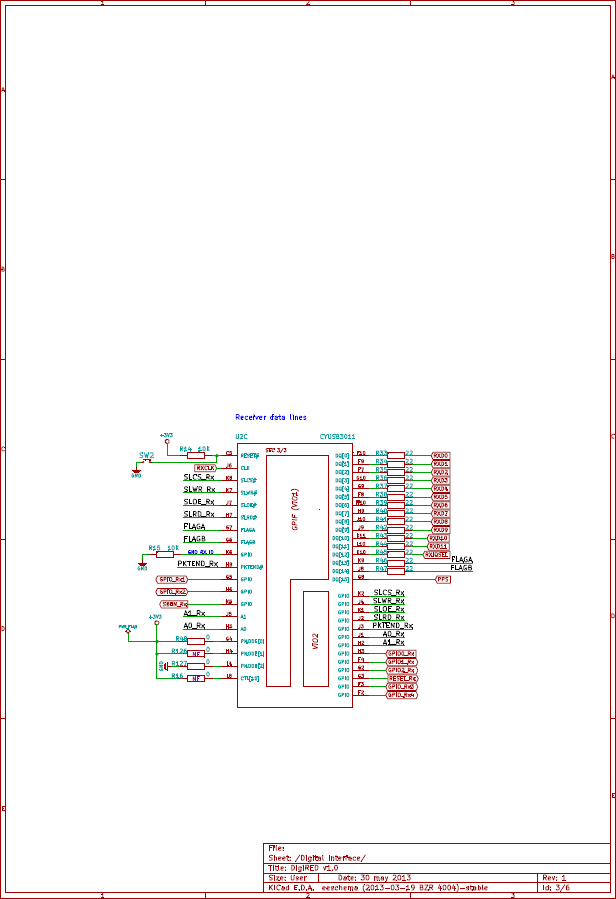
| 13:41, 15 September 2015 | Digired-digital-interface.png (file) |  |
38 KB | BogdanVacaliuc | page 2 of Digired schematic - transmit side cropped | 1 |
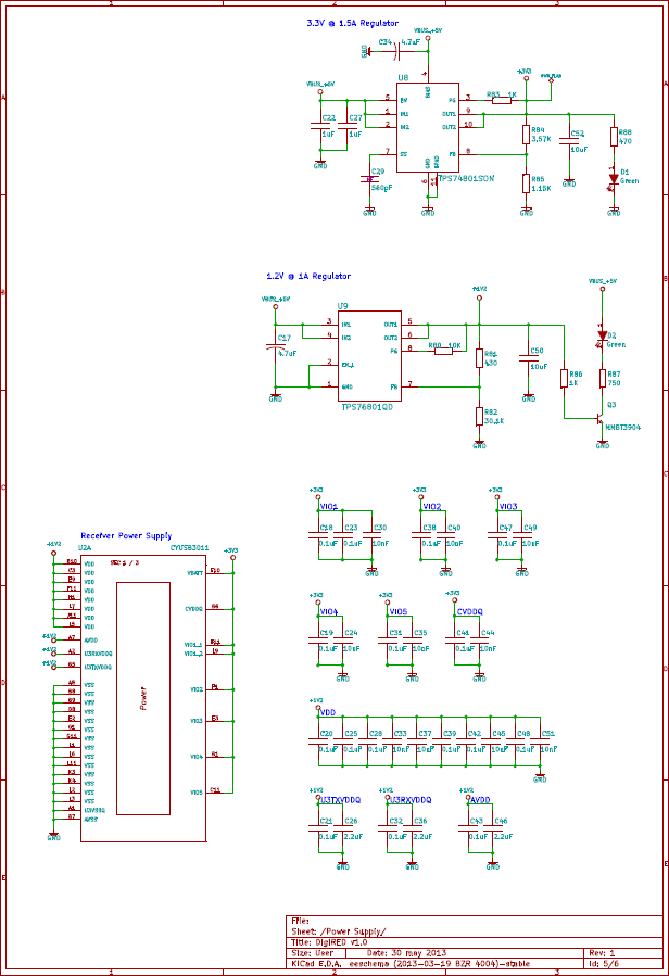
| 13:42, 15 September 2015 | Digired-power-supply.png (file) |  |
51 KB | BogdanVacaliuc | page 4 of Digired schematic - transmit side cropped | 1 |
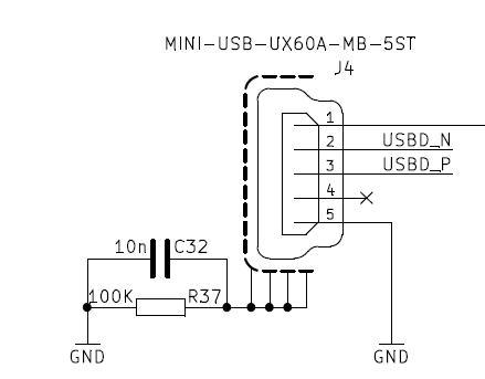
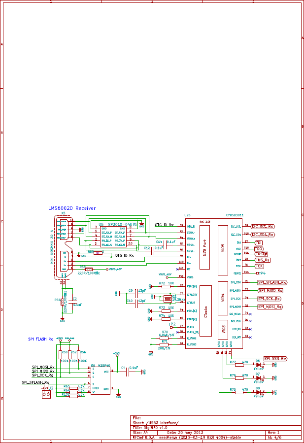
| 13:42, 15 September 2015 | Digired-usb3-interface.png (file) |  |
50 KB | BogdanVacaliuc | page 3 of Digired schematic - transmit side cropped | 1 |
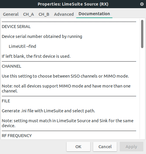
| 16:18, 8 February 2019 | Documentation Tab GnuRadio.png (file) |  |
44 KB | RicardasGarmus | 2 | |
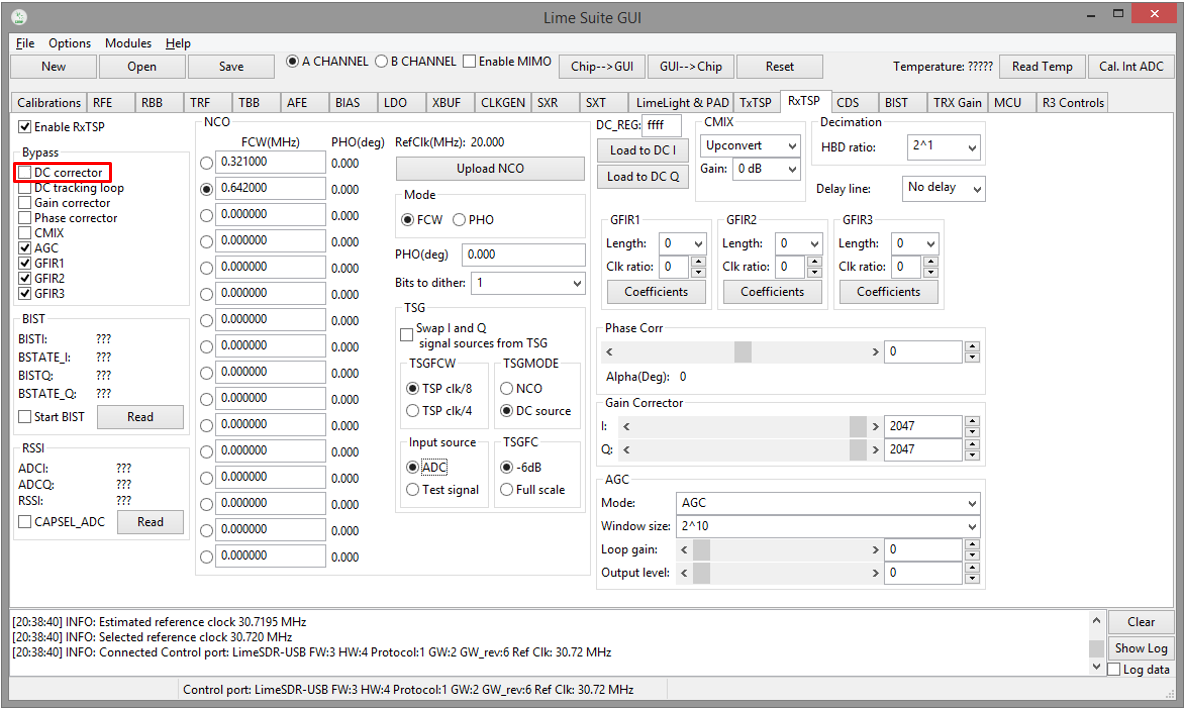
| 09:49, 29 August 2017 | Enable DC corrector in RxTSP.png (file) |  |
259 KB | ZydrunasTamosevicius | 1 | |
| 10:17, 29 August 2017 | Enable the test NCO.png (file) |  |
243 KB | ZydrunasTamosevicius | 1 | |
| 12:52, 8 March 2019 | Example.png (file) |  |
25 KB | VytautasBuitvydas | 1 | |
| 09:31, 29 August 2017 | FFTviewer Controls.png (file) |  |
80 KB | ZydrunasTamosevicius | 1 | |
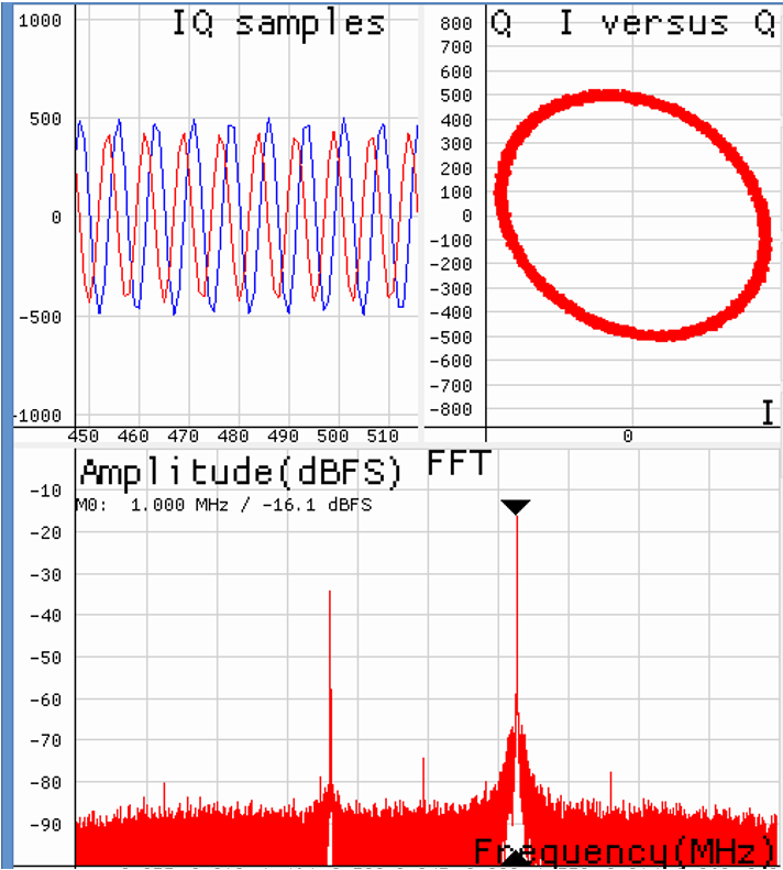
| 09:35, 29 August 2017 | FFTviewer window in operation.png (file) |  |
130 KB | ZydrunasTamosevicius | 1 | |
| 16:17, 8 February 2019 | FM Receiver Example GnuRadio.png (file) |  |
93 KB | RicardasGarmus | 2 | |
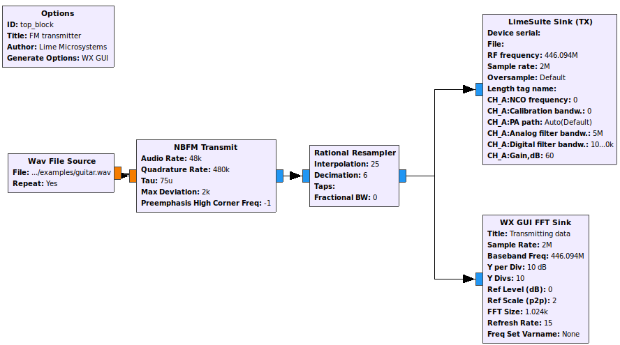
| 16:17, 8 February 2019 | FM Transmitter Example GnuRadio.png (file) | 70 KB | RicardasGarmus | 2 | ||
| 15:09, 10 September 2022 | FREEBSD Logo Horiz Pos RGB.png (file) | 33 KB | Cederom | 1 | ||
| 10:02, 30 August 2017 | FX3 after custom firmware is downloaded.png (file) |  |
161 KB | ZydrunasTamosevicius | 1 | |
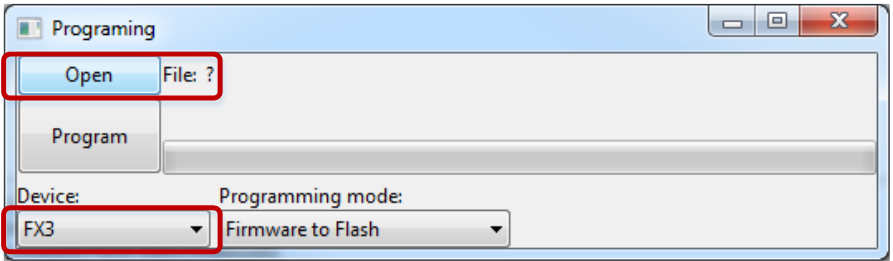
| 09:40, 30 August 2017 | FX3 programing options.png (file) |  |
61 KB | ZydrunasTamosevicius | 1 | |
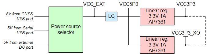
| 12:03, 11 April 2019 | Figure 10 Lime-GPSDO board power distribution block diagram.png (file) | 10 KB | VytautasBuitvydas | 1 | ||
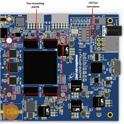
| 16:14, 8 March 2019 | Figure 11 LimeSDR-QPCIe v1.2 Dedicated FAN mounting space.png (file) |  |
226 KB | VytautasBuitvydas | 1 | |
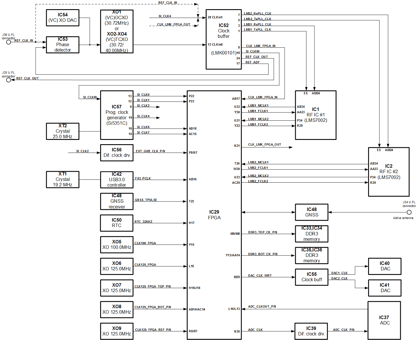
| 16:19, 8 March 2019 | Figure 12 LimeSDR-QPCIe v1.2 board clock distribution block diagram.png (file) |  |
85 KB | VytautasBuitvydas | 1 | |
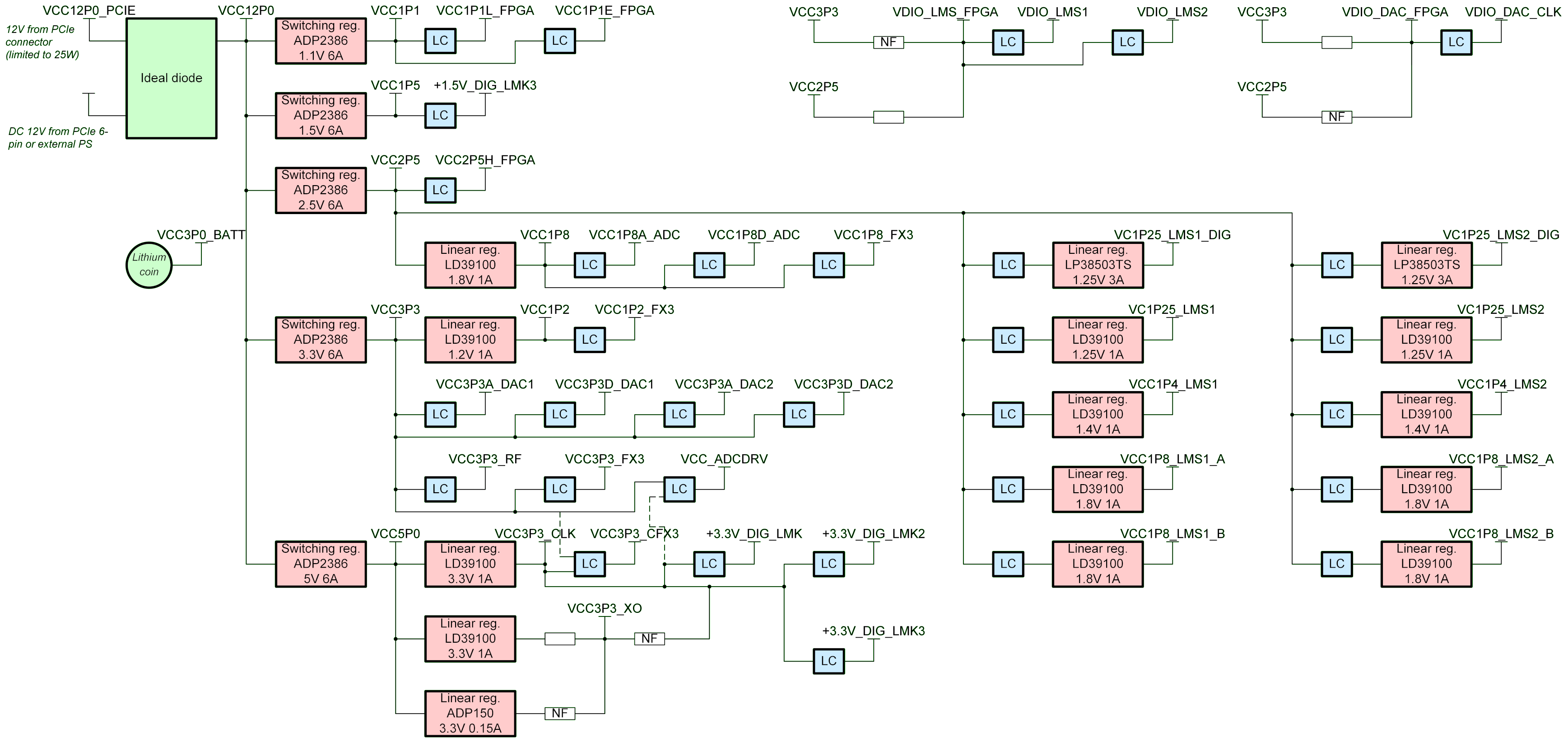
| 10:01, 12 March 2019 | Figure 13 LimeSDR-QPCIe v1.2 board power distribution block diagrams.png (file) |  |
536 KB | VytautasBuitvydas | 4 | |
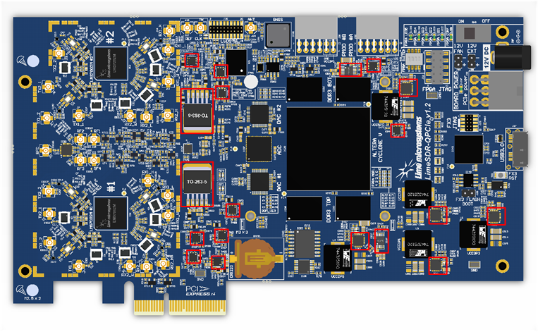
| 10:09, 12 March 2019 | Figure 14 LimeSDR-QPCIe v1.2 board power ICs on TOP side.png (file) |  |
475 KB | VytautasBuitvydas | 1 | |
| 10:10, 12 March 2019 | Figure 15 LimeSDR-QPCIe v1.2 board power ICs on BOTTOM side.png (file) |  |
505 KB | VytautasBuitvydas | 1 | |
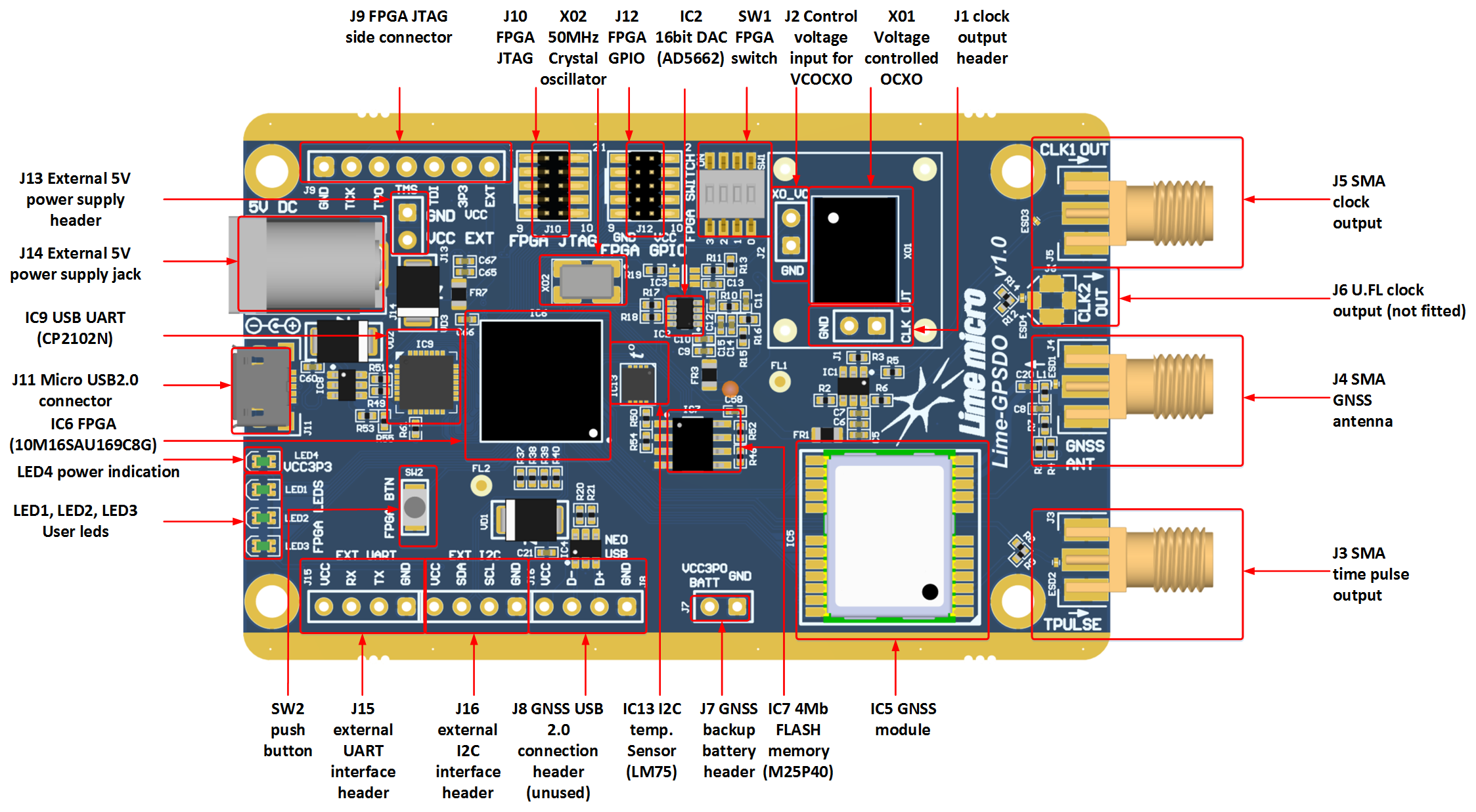
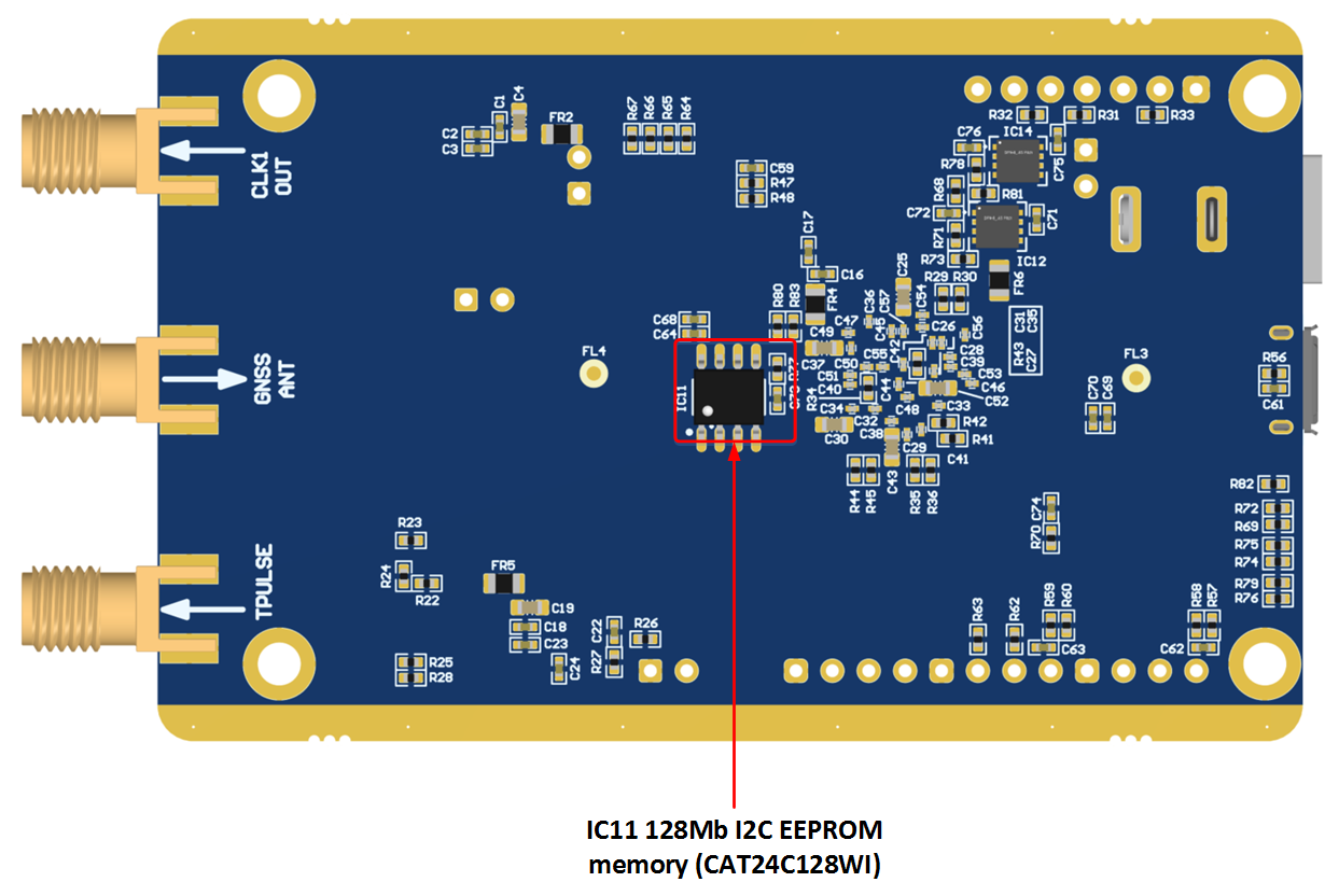
| 08:24, 11 April 2019 | Figure 1 Lime-GPSDO top side components and connectors.png (file) |  |
815 KB | VytautasBuitvydas | 1 | |
| 08:27, 11 April 2019 | Figure 2 Bottom side components.png (file) |  |
351 KB | VytautasBuitvydas | 1 | |
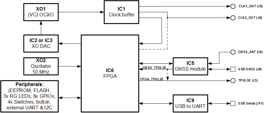
| 08:53, 11 April 2019 | Figure 3 Lime-GPSDO Development Board Block Diagram.png (file) |  |
20 KB | VytautasBuitvydas | 1 | |
| 09:36, 11 April 2019 | Figure 4 Time pulse output selection.png (file) |  |
95 KB | VytautasBuitvydas | 1 | |
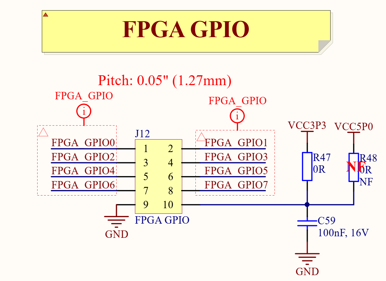
| 09:42, 11 April 2019 | Figure 5 Power rail selection for pin 10 of J12 connector.png (file) |  |
96 KB | VytautasBuitvydas | 1 | |
| 10:23, 11 April 2019 | Figure 6 Communication interfaces.png (file) |  |
15 KB | VytautasBuitvydas | 1 | |
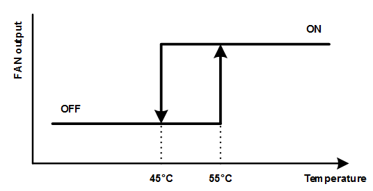
| 10:32, 11 April 2019 | Figure 7 FAN control temperature hysteresis.png (file) |  |
5 KB | VytautasBuitvydas | 1 | |
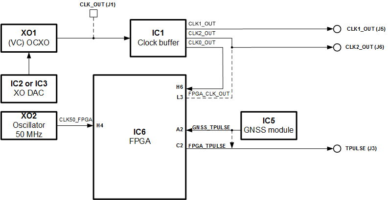
| 10:37, 11 April 2019 | Figure 8 Lime-GPSDO board clock distribution block diagram.png (file) |  |
16 KB | VytautasBuitvydas | 1 |