Uploads by Ghalfacree
Jump to navigation
Jump to search
This special page shows all uploaded files.
| Date | Name | Thumbnail | Size | Description | Versions |
|---|---|---|---|---|---|
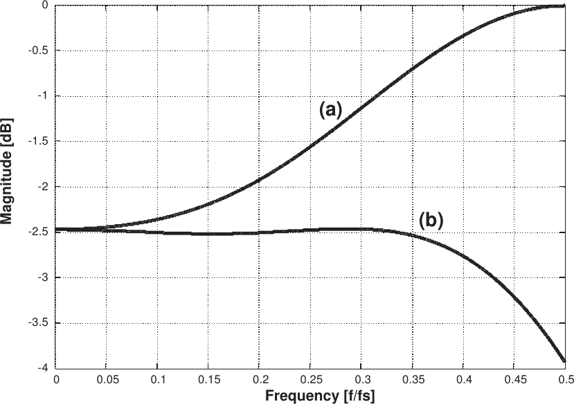
| 15:25, 2 June 2016 | Lms7002m-tsp-invsinc-dac-amplitude.png (file) |  |
39 KB | LMS7002M INVSINC (a) and corresponding DAC (b) amplitude response graph. | 1 |
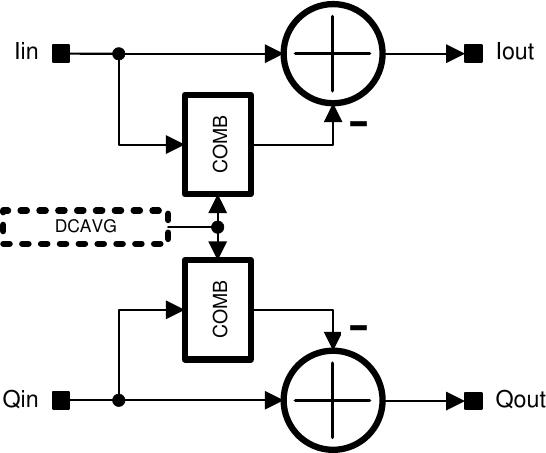
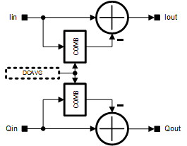
| 15:21, 2 June 2016 | Lms7002m-tsp-rx-dc-correction.png (file) |  |
18 KB | LMS7002M RX DC correction diagram. | 1 |
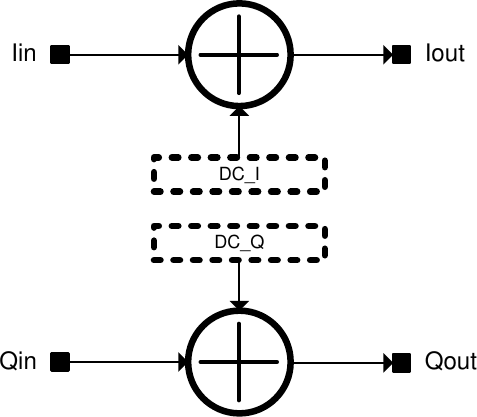
| 15:16, 2 June 2016 | Lms7002m-tsp-dc-offset.png (file) |  |
15 KB | LMS7002M DC offset diagram. | 1 |
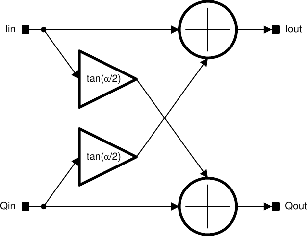
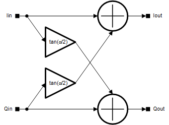
| 15:08, 2 June 2016 | Lms7002m-tsp-iq-phase-correction.png (file) |  |
24 KB | LMS7002M IQ phase correction diagram. | 1 |
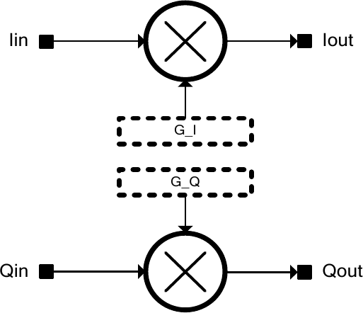
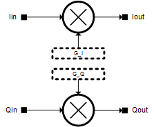
| 14:59, 2 June 2016 | Lms7002m-tsp-iq-gain-correction.png (file) |  |
17 KB | LMS7002M IQ gain correction diagram. | 1 |
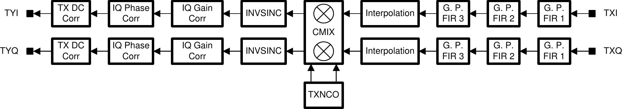
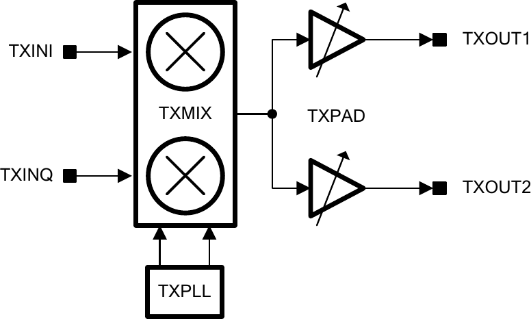
| 14:56, 2 June 2016 | Lms7002m-tsp-tx.png (file) | 54 KB | LMS7002M TXTSP structure diagram. | 1 | |
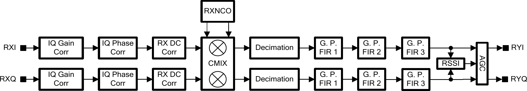
| 14:55, 2 June 2016 | Lms7002m-tsp-rx.png (file) | 61 KB | LMS7002M RXTSP structure diagram. | 1 | |
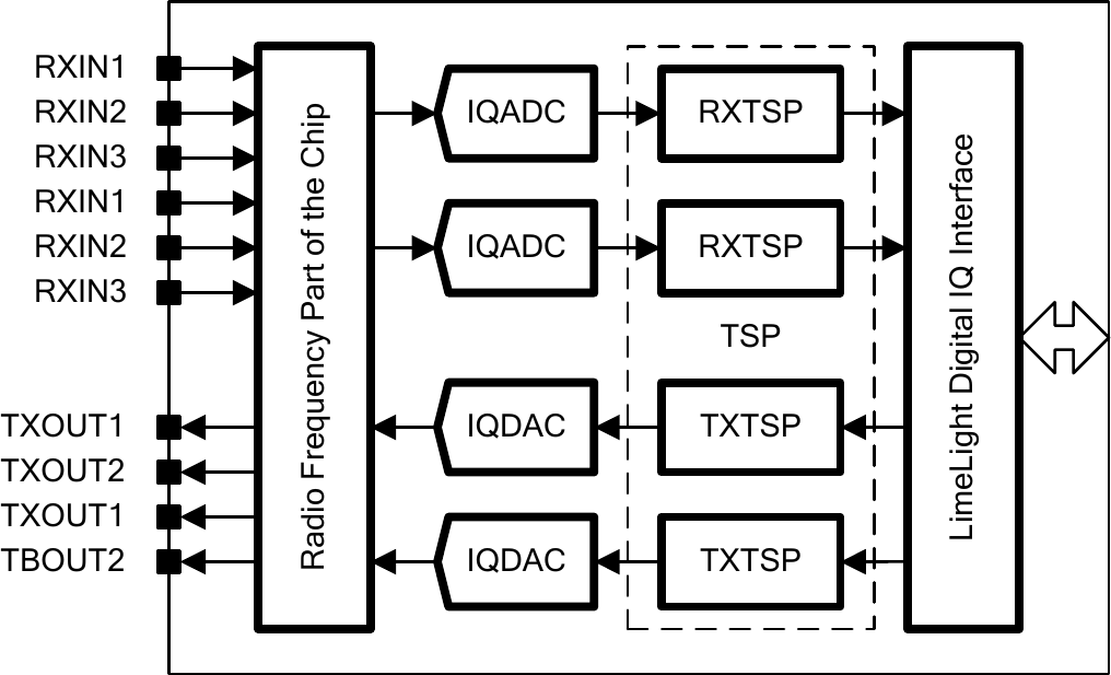
| 14:48, 2 June 2016 | Lms7002m-tsp.png (file) |  |
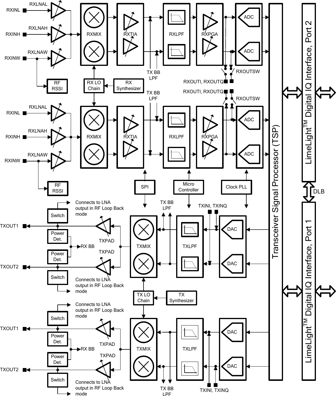
64 KB | LMS7002M Transceiver Signal Processor (TSP) block diagram. | 1 |
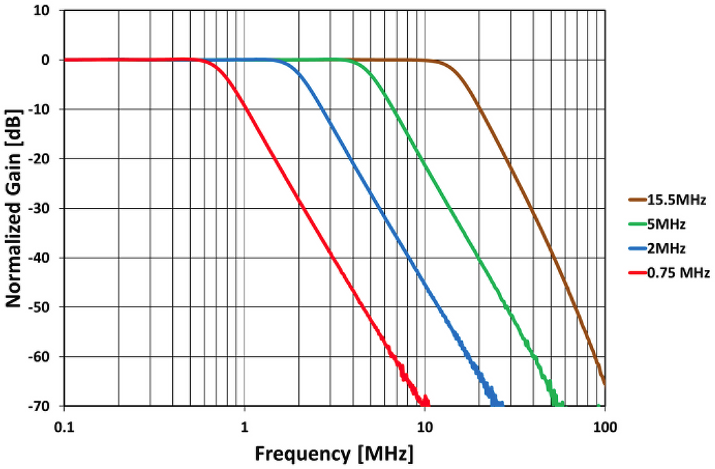
| 14:44, 2 June 2016 | Lms7002m-analogue-rx-lpfl-amplitude.png (file) |  |
199 KB | LMS7002M analogue RX LPFL amplitude graph. | 1 |
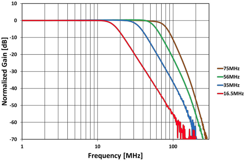
| 14:43, 2 June 2016 | Lms7002m-analogue-rx-lpfh-amplitude.png (file) |  |
191 KB | LMS7002M analogue RX LPFH amplitude graph. | 1 |
| 14:39, 2 June 2016 | Lms7002m-analogue-tx-lpfl-amplitude.png (file) |  |
182 KB | LMS7002M analogue TX LPFL amplitude graph. (Corrected typo in description) | 2 |
| 14:36, 2 June 2016 | Lms7002m-analogue-tx-lpfh-amplitude.png (file) |  |
171 KB | LMS7002M analogue TX LPFH amplitude graph. | 1 |
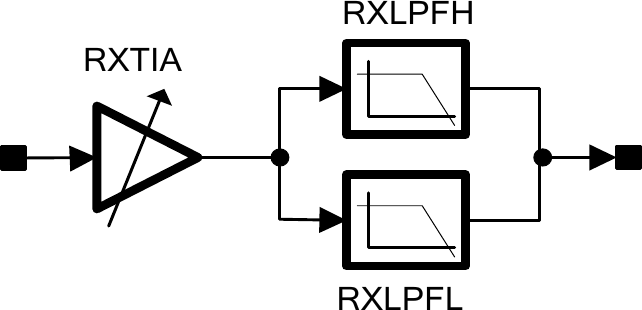
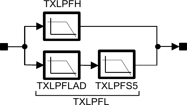
| 14:32, 2 June 2016 | Lms7002m-rx-analogue-filter-chain.png (file) |  |
13 KB | LMS7002M RX analogue filter chain diagram. | 1 |
| 14:28, 2 June 2016 | Lms7002m-tx-analogue-filter-chain.png (file) |  |
13 KB | LMS7002M TX analogue filter chain diagram. | 1 |
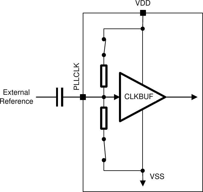
| 16:05, 1 June 2016 | Lms7002m-pll-reference-clock-input-buffer-ac-coupled.png (file) |  |
18 KB | LMS7002M PLL reference clock input buffer, AC coupled. | 1 |
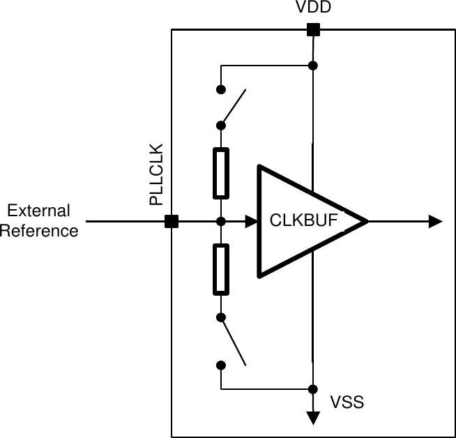
| 16:04, 1 June 2016 | Lms7002m-pll-reference-clock-input-buffer-dc-coupled.png (file) |  |
18 KB | LMS7002M PLL reference clock input buffer, DC coupled. | 1 |
| 16:01, 1 June 2016 | Lms7002m-pll-architecture.png (file) |  |
23 KB | LMS7002M PLL architecture diagram. | 1 |
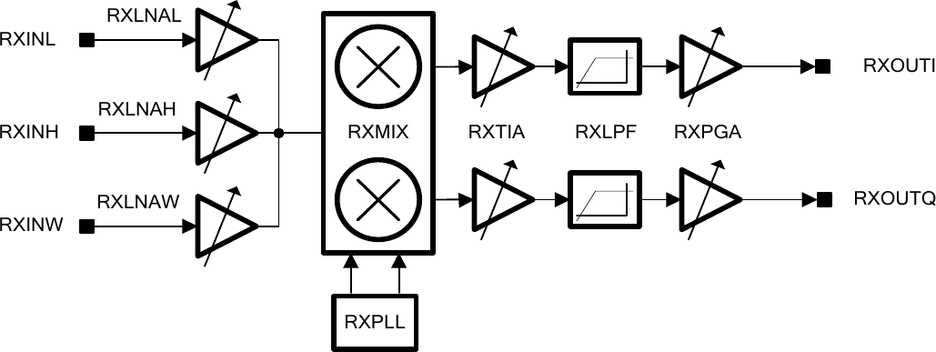
| 15:55, 1 June 2016 | Lms7002m-rx-gain-control-architecture.png (file) |  |
35 KB | LMS7002M RX gain control architecture diagram. | 1 |
| 15:50, 1 June 2016 | Lms7002m-analogue-gain-control-architecture.png (file) |  |
26 KB | LMS7002M analogue/RF gain control architecture diagram. | 1 |
| 15:18, 1 June 2016 | Lms7002m-functional-block-diagram.png (file) |  |
214 KB | LMS7002M functional block diagram. | 1 |
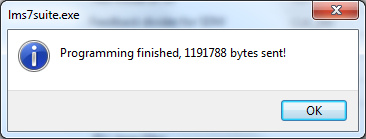
| 19:38, 4 May 2016 | LimeSDR-USB-LMS-7-Suite-Modules-Programming-Complete.jpg (file) |  |
20 KB | LMS 7 Suite confirming programming of an FPGA with a new bitstream. | 1 |
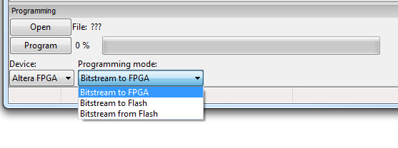
| 19:37, 4 May 2016 | LimeSDR-USB-LMS-7-Suite-Modules-Programming-Mode.jpg (file) |  |
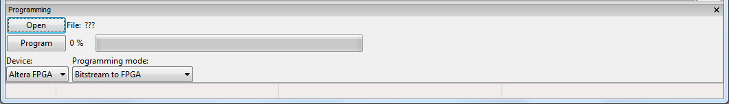
35 KB | Choosing a programming mode in the LMS 7 Suite. | 1 |
| 19:36, 4 May 2016 | LimeSDR-USB-LMS-7-Suite-Modules-Programming-Section.jpg (file) | 33 KB | LMS 7 Suite showing the programming section. | 1 | |
| 19:36, 4 May 2016 | LimeSDR-USB-LMS-7-Suite-Modules-Programming.jpg (file) |  |
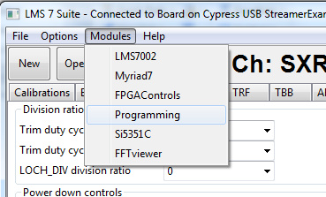
57 KB | LMS 7 Suite software showing the Modules menu. | 1 |
| 19:28, 4 May 2016 | LimeSDR-USB-LMS7002-GUI-ConnectionSettings.jpg (file) |  |
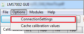
24 KB | LMS7002 GUI software showing ConnectionSettings option in Options menu. | 1 |
| 21:03, 3 May 2016 | LimeSDR-FX3-Firmware-RAM.jpg (file) |  |
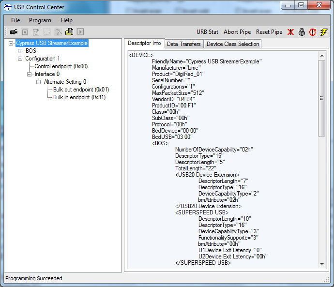
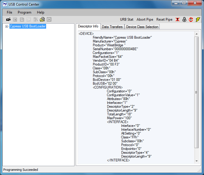
163 KB | The USB Control Center software showing a LimeSDR-USB after new firmware has been uploaded to the FX3 controller RAM. | 1 |
| 20:56, 3 May 2016 | LimeSDR-USB-Control-Center.jpg (file) |  |
134 KB | The USB Control Center software showing a LimeSDR-USB booted from factory default firmware. | 1 |
| 20:51, 3 May 2016 | LimeSDR-USB-Windows-USB-Driver-Installation-4.jpg (file) |  |
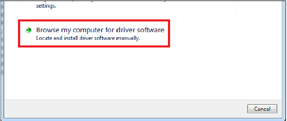
51 KB | LimeSDR-USB Windows driver installation, step 4. | 1 |
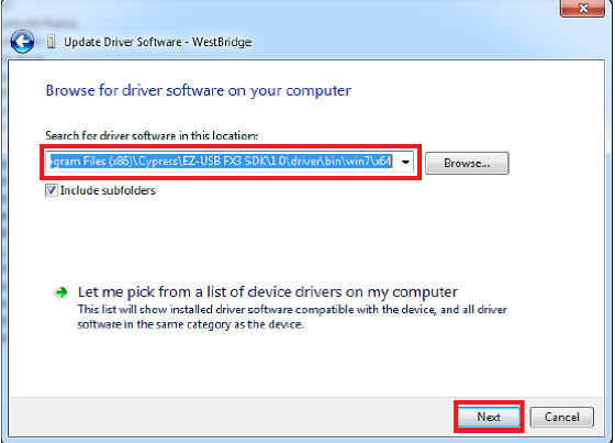
| 20:45, 3 May 2016 | LimeSDR-USB-Windows-USB-Driver-Installation-3-3.jpg (file) |  |
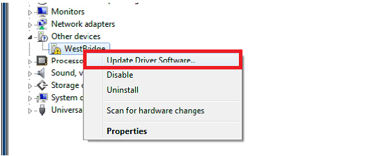
81 KB | LimeSDR-USB Windows driver installation, step 3 part 3. | 1 |
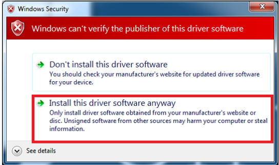
| 20:45, 3 May 2016 | LimeSDR-USB-Windows-USB-Driver-Installation-3-2.jpg (file) |  |
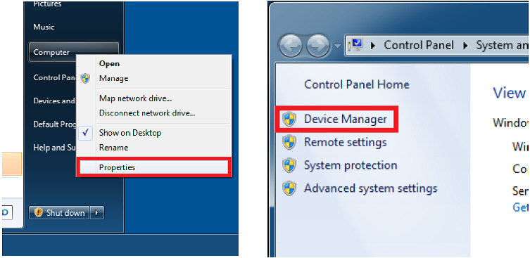
68 KB | LimeSDR-USB Windows driver installation, step 3 part 2. | 1 |
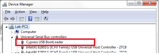
| 20:38, 3 May 2016 | LimeSDR-USB-Windows-USB-Driver-Installation-3.jpg (file) |  |
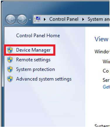
25 KB | LimeSDR-USB Windows driver installation, step 3. | 1 |
| 20:34, 3 May 2016 | LimeSDR-USB-Windows-USB-Driver-Installation-2.jpg (file) |  |
36 KB | LimeSDR-USB Windows driver installation, step two. | 1 |
| 20:30, 3 May 2016 | LimeSDR-USB-Windows-USB-Driver-Installation-1.jpg (file) |  |
94 KB | Combined two figures into one for easier embedding. | 2 |
| 20:27, 3 May 2016 | LimeSDR-USB-Windows-USB-Driver-Installation-1-Continued.jpg (file) |  |
53 KB | LimeSDR-USB Windows driver installation, step one (continued.) | 1 |
| 20:09, 3 May 2016 | LimeSDR-USB-Power-Block-Diagram.jpg (file) |  |
97 KB | Block diagram for the LimeSDR-USB v1.2's power circuitry. | 1 |
| 20:09, 3 May 2016 | LimeSDR-USB-Power-Circuits.jpg (file) |  |
274 KB | The LimeSDR-USB v1.2's power circuitry, highlighted. | 1 |
| 20:05, 3 May 2016 | LimeSDR-USB-Clock-Distribution.jpg (file) |  |
46 KB | Block diagram for the LimeSDR-USB v1.2's clock distribution. | 1 |
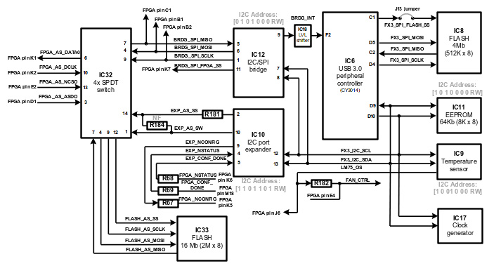
| 19:59, 3 May 2016 | LimeSDR-USB-FPGA-Low-Speed-Interfaces-Block-Diagram.jpg (file) |  |
55 KB | Block diagram for the FPGA low-speed interfaces on the LimeSDR-USB v1.2. | 1 |
| 19:55, 3 May 2016 | LimeSDR-USB-FX3-Low-Speed-Interfaces-Block-Diagram.jpg (file) |  |
72 KB | Block diagram for the low-speed interfaces on the LimeSDR-USB v1.2. | 1 |
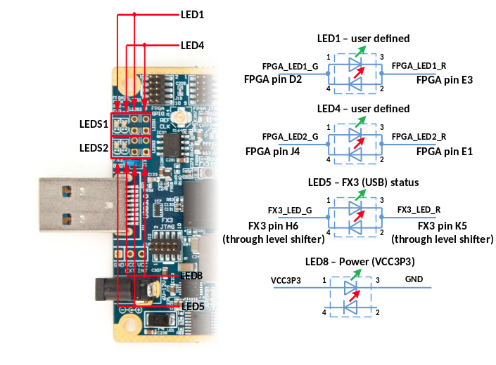
| 19:48, 3 May 2016 | LimeSDR-USB-LEDs.jpg (file) |  |
115 KB | LimeSDR-USB v1.2 LED diagram. | 1 |
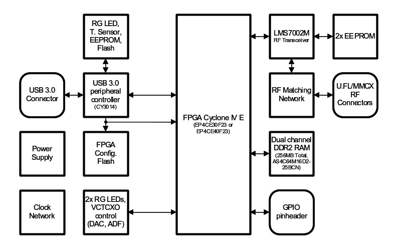
| 16:40, 3 May 2016 | LimeSDR-USB-Block-Diagram.jpg (file) |  |
62 KB | LimeSDR-USB block diagram. | 1 |
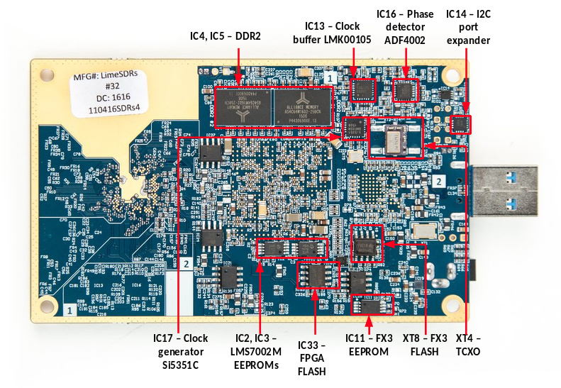
| 16:38, 3 May 2016 | LimeSDR-USB-Components-Bottom-Side.jpg (file) |  |
245 KB | LimeSDR-USB v1.2 board components, bottom side (labelled). | 1 |
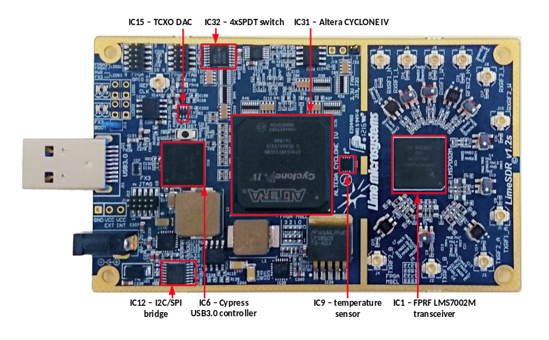
| 16:36, 3 May 2016 | LimeSDR-USB-Components-Top-Side.jpg (file) |  |
176 KB | LimeSDR-USB v1.2 board, top-side components (labelled). | 1 |
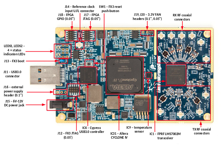
| 15:58, 3 May 2016 | LimeSDR-USB-Overview.jpg (file) |  |
196 KB | LimeSDR-USB v1.2 board, labelled overview (top side). | 1 |
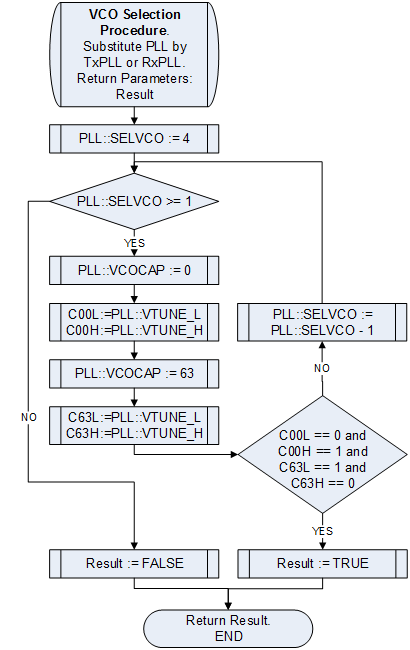
| 15:45, 13 October 2015 | LMS6002Dr2-VCO-VCOCAP-Code-Selection-Algorithm-VCO-Selection.png (file) |  |
20 KB | Improved graphic. | 2 |
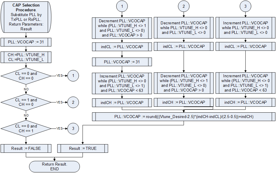
| 15:44, 13 October 2015 | LMS6002Dr2-VCO-VCOCAP-Code-Selection-Algorithm-VCOCAP-Selection.png (file) |  |
39 KB | Improved graphic. | 2 |
| 15:44, 13 October 2015 | LMS6002Dr2-IQ-Gain-Correction.png (file) |  |
5 KB | Improved graphic. | 2 |
| 15:44, 13 October 2015 | LMS6002Dr2-IQ-Phase-Correction.png (file) |  |
7 KB | Improved graphic. | 2 |
| 15:43, 13 October 2015 | LMS6002Dr2-RX-I-Q-DC-Level-Correction.png (file) |  |
6 KB | Improved graphic. | 2 |
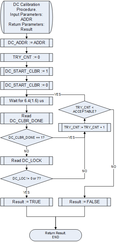
| 15:40, 13 October 2015 | LMS6002Dr2-General-DC-Calibration.png (file) |  |
20 KB | Updated diagram. | 2 |