Myriad-RF 1: Difference between revisions
Ghalfacree (talk | contribs) m (Switched to much nicer gallery layout for the images & added block diagram.) |
Ghalfacree (talk | contribs) (Added schematics as a gallery.) |
||
| Line 41: | Line 41: | ||
===Schematics=== | ===Schematics=== | ||
<gallery> | |||
File:MyriadRF-Schematics-1.png|RF circuits | |||
File:MyriadRF-Schematics-2.png|Analogue circuits | |||
File:MyriadRF-Schematics-3.png|Clocks, RF FE | |||
File:MyriadRF-Schematics-4.png|Connectors | |||
File:MyriadRF-Schematics-5.png|Digital circuits | |||
File:MyriadRF-Schematics-6.png|Power supply | |||
</gallery> | |||
===See Also=== | ===See Also=== | ||
Revision as of 14:36, 16 July 2015
About
The Myriad–RF 1 board is a multi-band, multi-standard RF module, based on the LMS6002D transceiver IC by Lime Microsystems. It has one RF broadband output, one RF broadband input with digital baseband interface, established via a standard Hirose FX10A-80P connector. The board also provides the user with pin headers for power supply, reference clock, analogue input/output and Serial Peripheral Interface (SPI) connections. It contains everything needed for it to be connected to baseband (BB) chipsets, Field-Programmable Gate Arrays (FPGAs), or to run independently in an standalone mode.
The Myriad-RF 1 board enables developers implement their products for a wide variety of wireless communication applications quickly and efficiently, given the flexibility of the solution. In addition, the designer can make use of the freely available ready-made board implementation, modify and manufacture to accelerate the development time.
Images
-
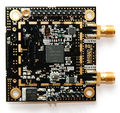
Myriad-RF 1, top
-
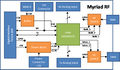
Myriad-RF 1 block diagram


Specifications
| Transceiver | LMS6002D |
| RF Bandwidth (BW) | 300 MHz to 3800 MHz |
| Baseband Bandiwdth (BW) | Programmable (16 selections:; 0.75 – 14 MHz, Bypass mode |
| RF Module Control | Via Serial Peripheral Interface (SPI) |
| Analogue Inputs | I/Q differential analogue input for transmitter |
| Analogue Outputs | I/Q differential analogue output from receiver |
| Reference Clock Frequency | 23 – 41 MHz |
| Input Voltage | 5 V(recommended) |
Connections
The Myriad-RF 1 board can be used as a standalone board or in conjunction with the DE0-Nano Interface Board or Zipper Interface Board. The analogue differential IQ interface is also available directly on the Myriad-RF 1 board, along with RF connections. A full list of available connections is available on the page Myriad-RF 1 Connections.
Schematics
-

RF circuits
-

Analogue circuits
-

Clocks, RF FE
-

Connectors
-

Digital circuits
-

Power supply


