Uncategorized files
Jump to navigation
Jump to search
Showing below up to 50 results in range #71 to #120.
-
Digired-clock-generator.png 616 × 899; 56 KB
-
Digired-connectors.png 616 × 899; 62 KB
-
Digired-digital-interface.png 616 × 899; 38 KB
-
Digired-power-supply.png 616 × 899; 51 KB
-
Digired-usb3-interface.png 617 × 899; 50 KB
-
Documentation Tab GnuRadio.png 500 × 528; 44 KB
-
Enable DC corrector in RxTSP.png 1,185 × 709; 259 KB
-
Enable the test NCO.png 1,187 × 706; 243 KB
-
Example.png 384 × 190; 25 KB
-
FFTviewer Controls.png 679 × 476; 80 KB
-
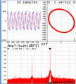
FFTviewer window in operation.png 712 × 791; 130 KB
-
FM Receiver Example GnuRadio.png 1,183 × 491; 93 KB
-
FM Transmitter Example GnuRadio.png 888 × 495; 70 KB
-
FREEBSD Logo Horiz Pos RGB.png 570 × 164; 33 KB
-
FX3 after custom firmware is downloaded.png 701 × 610; 161 KB
-
FX3 programing options.png 893 × 261; 61 KB
-
Figure 10 Lime-GPSDO board power distribution block diagram.png 677 × 183; 10 KB
-
Figure 11 LimeSDR-QPCIe v1.2 Dedicated FAN mounting space.png 433 × 432; 226 KB
-
Figure 12 LimeSDR-QPCIe v1.2 board clock distribution block diagram.png 1,457 × 1,186; 85 KB
-
Figure 13 LimeSDR-QPCIe v1.2 board power distribution block diagrams.png 3,473 × 1,643; 536 KB
-
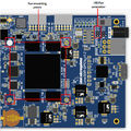
Figure 14 LimeSDR-QPCIe v1.2 board power ICs on TOP side.png 763 × 471; 475 KB
-
Figure 15 LimeSDR-QPCIe v1.2 board power ICs on BOTTOM side.png 767 × 473; 505 KB
-
Figure 1 Lime-GPSDO top side components and connectors.png 2,247 × 1,237; 815 KB
-
Figure 2 Bottom side components.png 1,243 × 832; 351 KB
-
Figure 3 Lime-GPSDO Development Board Block Diagram.png 869 × 373; 20 KB
-
Figure 4 Time pulse output selection.png 1,455 × 904; 95 KB
-
Figure 5 Power rail selection for pin 10 of J12 connector.png 1,252 × 911; 96 KB
-
Figure 6 Communication interfaces.png 868 × 362; 15 KB
-
Figure 7 FAN control temperature hysteresis.png 536 × 275; 5 KB
-
Figure 8 Lime-GPSDO board clock distribution block diagram.png 793 × 410; 16 KB
-
Figure 9 LimeSDR-QPCIe v1.2 indication LEDs.png 463 × 382; 120 KB
-
Figure 9 SMA connector J6 source selection.png 1,336 × 759; 70 KB
-
Freebsd-128-128.png 132 × 128; 36 KB
-
Freebsd-logo.png 178 × 175; 32 KB
-
GFSK loopback example.png 990 × 481; 105 KB
-
Git logo.png 155 × 80; 4 KB
-
Gpredict 1 768w.jpg 768 × 656; 164 KB
-
Grc xmit only.jpg 781 × 246; 39 KB
-
IQ Corrector block control.png 1,186 × 708; 243 KB
-
KiCAD footprints.png 700 × 478; 321 KB
-
Kill Flow Graph Button GnuRadio.png 141 × 36; 4 KB
-
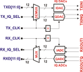
LMS6002D-Baseband-Data-Interface.png 1,324 × 1,149; 121 KB
-
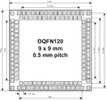
LMS6002D-DQFN120-Package-Top-View.png 1,386 × 1,298; 153 KB
-
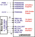
LMS6002D-Digital-IQ-Interface-Supplies.png 1,146 × 1,196; 155 KB
-
LMS6002D-Frame-Sync-Polarity-Interleave-Modes.png 2,262 × 1,210; 166 KB
-
LMS6002D-Functional-Block-Diagram.png 3,149 × 2,425; 475 KB
-
LMS6002D-LPF-Amplitude-Response-1.png 706 × 546; 34 KB
-
LMS6002D-LPF-Amplitude-Response-2.png 706 × 546; 34 KB
-
LMS6002D-PLL-Architecture.png 1,927 × 1,446; 106 KB
-
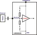
LMS6002D-PLL-Reference-Clock-Input-Buffer-AC-Coupled.png 1,820 × 1,734; 95 KB


