ClockTamerGPS
Introduction
ClockTamer has the ability to lock its clock to GPS, providing much higher stability then you can get from any TCXO or VCTCXO. To lock to GPS it uses a 1pps signal, generated by many GPS chips. The ClockTamer microcontroller then counts the number of clock pulses on one of the generator outputs between consecutive 1pps pulses and applies math filtering to get real (VC)TCXO frequency. Knowing the real (VC)TCXO frequency we are able to compensate it in software.
There are two options of getting 1pps signal:
- Use external GPS unit with 1pps input. ClockTamer have a placeholder for 1pps U.FL connector (TODO: Picture). If you already have GPS unit with 1pps output and you don't care about physical size, that's your choice.
- Solder GPS ship right on ClockTamer unit (on the back side of PCB). This makes ClockTamer slightly more expensive, but you don't need any external device anymore! You save in physical space and avoid headaches with wiring devices together.
With GPS locking it's not critical to have a very high precision XO, so it's possible to use a 2.5ppm VCTCXO option instead of standard 0.28ppm TCXO. This is the configuration we use in our own experiments.
Note: When GPS-locking option is installed, you can only use 5 of the 6 ClockTamer outputs, since one output is routed to microcontroller. Exactly, output number 2 is not available TODO: Picture.
Usage
- When GPS lock is acquired, LED starts flashing with 2 sec period.
- If you want to detect GPS lock with automatically, use GPS debug register `R01`. Refer to control protocol documentation for details and to tamer-gui for an implementation example.
Frequency stability
The current implementation first reduces measurement jitter by averaging measurements for 17sec. Then calculated values are used as input for exponential filter to get fine resolution frequency measurement. Calculations are done with 32-bit precision.
Current implementation
- 32-bit precision of calculations imposes maximum achievable stability of 50ppb.
- From 11ppm filter converges to 1ppm for to 85sec, to 50ppb for 30min
- Filter can tolerate XO frequency drift of no more then 0.2ppm during 85sec.
See the wish list ways this may be improved.
GPS positioning mode
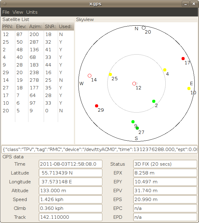
You could also use ClockTamer as a GPS positioning device. To switch from SPI command mode to GPS positioning mode use the %%% command. To leave GPS positioning mode and switch back to SPI command mode use the % command.
When in the GPS positioning mode it is possible to use ClockTamer with any application which understands NMEA protocol. Below is a picture of `xgps` application, reading data from a ClockTamer:
