ScratchRadio Programming
Program Structure
All Scratch Radio programs will have the same underlying structure consisting of two distinct phases. The radio setup phase is used to configure the way the radio will operate by connecting various radio blocks together. The radio operation phase then activates the radio and allows the radio to transmit and receive radio signals as required.
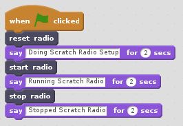
There are three Scratch Radio blocks which are used to control these phases of operation – the reset, start and stop blocks. The reset block is used to discard any previous radio configuration and prepare the radio at the start of the setup phase. Once the radio has been configured, the start block is used to activate the radio at the start of the operation phase. Finally, the stop block is used to halt the radio at the end of the operation phase. This means that all Scratch Radio programs will have a structure similar to the one shown below:
Flow Graph Setup
The setup phase of a Scratch Radio program is used to connect various radio blocks together into a data flow graph to create a complete radio system. Scratch Radio blocks which may be used during the setup phase are indicated by the use of a flow graph icon at the left hand side of the Scratch block. These icons have the following meanings:
![]() Data Flow Source – This icon is used to indicate that the flow graph block is a data input. When the radio is active, data will be received from some external data producer and emitted at the output of the block.
Data Flow Source – This icon is used to indicate that the flow graph block is a data input. When the radio is active, data will be received from some external data producer and emitted at the output of the block.
![]() Data Flow Sink – This icon is used to indicate that the flow graph block is a data output. When the radio is active, data will be accepted at the input to the block and emitted to some external data consumer.
Data Flow Sink – This icon is used to indicate that the flow graph block is a data output. When the radio is active, data will be accepted at the input to the block and emitted to some external data consumer.
![]() Data Flow Process – This icon is used to indicate that the flow graph block is a data processing block. When the radio is active, data will be accepted at the input of the block and processed, with the transformed data being emitted at the output of the block.
Data Flow Process – This icon is used to indicate that the flow graph block is a data processing block. When the radio is active, data will be accepted at the input of the block and processed, with the transformed data being emitted at the output of the block.
![]() Data Flow Tap – This icon is used to indicate that the flow graph block taps into the data being produced elsewhere in the flow graph and replicates it at the output of the block.
Data Flow Tap – This icon is used to indicate that the flow graph block taps into the data being produced elsewhere in the flow graph and replicates it at the output of the block.
