Getting Started with Lime-GPSDO
Basic setup
To get Lime-GPSDO board up and running:
- Connect GNSS antenna to J4 SMA connector (see Figure 1).
- Power up board through microUSB connector (see Figure 1) or 5V DC power jack (see chapter 3.8 Power Distribution and Figure 1 for other power options).

Board status
After connecting GNSS antenna and applying power you should see green color LED4 which indicates that board is getting power and red LED1 which indicates VCOCXO tune state which are listed below:
- Solid RED – no GPS lock, VCOCXO frequency tuning is off;
- Blinking RED – GPS is locked, 1s lowest accuracy tune state;
- Blinking RED/GREEN - GPS is locked, 10s accuracy tune state;
- Blinking GREEN - GPS is locked, 100s highest accuracy tune state.
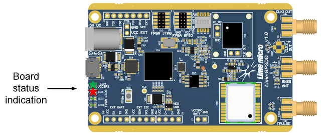
Usually GNSS module takes some time to gain GPS lock after applying power this means that LED1 will stay solid red and VCOCXO frequency tune process starts after GNSS module gains GPS lock and LED1 starts blinking.
Debug information
There is ability to get NMEA messages from GNSS module or VCOCXO tune log through onboard USB-to-UART bridge. For this example desktop PC running Windows 10 is used.
After connecting Lime-GPSDO microUSB to PC, you should see new COM port in “Device manager”
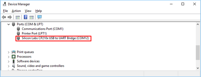
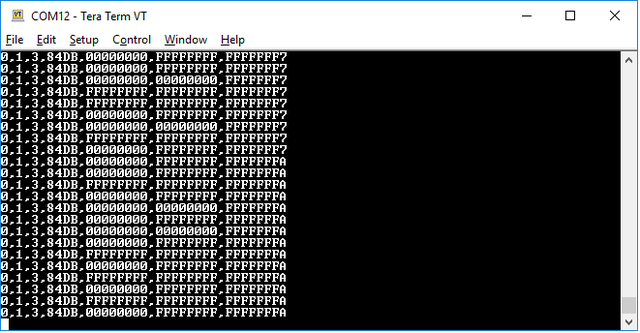
Then serial terminal with 9600 baud rate setting can be used to connect to COM port and get serial data. Set SW1.0 switch to ON position to get NMEA messages from GNSS module or SW1.0 switch to OFF and SW1.1 to ON position to get VCOCXO tune state log Figure 13. Log is printed in following format:
- Reserved,State,Accuracy,DAC val,1s,10s,100s
- State – 0 – coarse tune, 1 – Fine tune;
- Accuracy – 1 – 1s lowest accuracy state, 10s accuracy state, 100s highest accuracy state;
- DAC val – Current DAC value hexadecimal format;
- 1s – Frequency error (hexadecimal format) in clock cycles measured in 1s period;
- 10s – Frequency error (hexadecimal format) in clock cycles measured in 10s period;
- 100s – Frequency error (hexadecimal format) in clock cycles measured in 10s period.
- State – 0 – coarse tune, 1 – Fine tune;
Refer to chapter Switch and push button for slide switch description.
Results
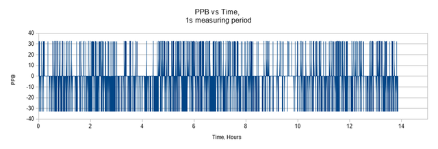
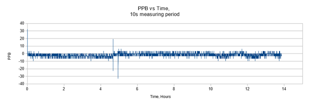
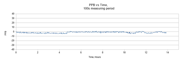
To evaluate Lime-GPSDO v1.0 clock accuracy and stability see charts below. Figure 5 – represents PPB measurement taken from one second period, Figure 6 – PPB measurement taken from 10 second period, Figure 7 – PPB measurement taken from 100 second period. Results were logged for approximately 14 hours. Measurements from 1 and 10 second period gives only rough estimate of clock stability because they give calculation error as large as ~30 PPB (1s measuring period) due to short measuring time. From 100s measuring period chart (Figure 16) results shows that Lime-GPSDO v1.0 board can achieve frequency stability of ±5 parts per billion.
