LimeSDR-Mini v1.1 hardware description: Difference between revisions
| Line 151: | Line 151: | ||
=== Power Distribution === | === Power Distribution === | ||
LimeSDR-Mini board is powered from USB port. LimeSDR-Mini board power delivery network consists of different power rails with different voltages, filters, power sequences. LimeSDR-Mini board power distribution block diagram is presented in Figure 9. | |||
Revision as of 08:22, 20 February 2018
LimeSDR-Mini Board Key Features
The LimeSDR-Mini is low-cost software defined radio board. LimeSDR-Mini development board provides a hardware platform for developing and prototyping high-performance and logic-intensive digital and RF designs using Intel’s MAX 10 FPGA and Lime Microsystems transceiver.

LimeSDR-Mini board features:
- USB 3.0 controller: FTDI FT601
- FPGA: Intel MAX 10 (10M16SAU169C8G 169-UBGA)
- 169-pin FBGA package
- 16 K LE
- 549 Kb M9K Memory
- 2368 Kb User Flash Memory
- 1x fractional phase locked loops (PLLs)
- 45x 18x18-bit multipliers
- 130x general purpose input/output (GPIO)
- Single supply
- Flash feature
- FPGA configuration via JTAG
- RF transceiver: Lime Microsystems LMS7002M
- EEPROM Memory: 2x 128Kb EEPROMs for LMS MCU firmware and FPGA data
- FLASH Memory: 4Mb Flash memory for FPGA data
- Temperature sensor (unpopulated)
- General user inputs/outputs:
- 1x Dual colour (RG) LED
- 8x + 2x FPGA GPIO pinheader (3.3V)
- Connections:
- USB3.0 (type A) plug
- Coaxial RF (SMA female) connectors
- FPGA GPIO headers (unpopulated)
- FPGA JTAG connector (unpopulated)
- FAN (5V or 3.3V) connector
- Clock system:
- 40.00MHz onboard VCTCXO
- Possibility to trim VCTCXO by onboard DAC
- Reference clock input and output connectors (U.FL)
- Board size: 69mm x 31.4mm
For more information on the following topics, refer to the respective documents:
- FTDI FT601 USB 3.0 to FIFO Bridge datasheet [link]
- MAX 10 FPGA device family, refer to MAX 10 Device Handbook [link]
- LMS7002M transceiver resources [link]
Board Overview
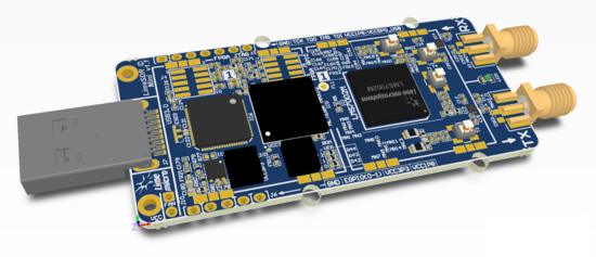
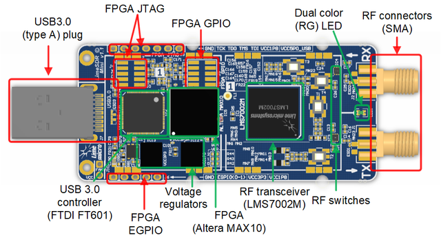
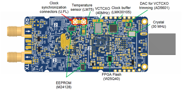
This section contains component location description on the board. LimeSDR-Mini board picture with highlighted connectors and main components is presented in Figure 2 and Figure 3.


Board components description listed in the Table 1.
| Featured Devices | ||
|---|---|---|
| Board reference | Type | Description |
| IC1 | FPRF | Field programmable RF transceiver, LMS7002M |
| IC5 | FPGA | Intel MAX 10 (10M16SAU169C8G 169-UBGA) |
| IC6 | USB 3.0 microcontroller | Intel MAX 10 (10M16SAU169C8G 169-UBGA) |
| Miscellaneous devices onboard | ||
| IC8 | IC | Temperature sensor, LM75 |
| Configuration, Status and Setup Components | ||
| J3 | JTAG chain connector | FPGA programming pin header on the board edge for Altera USB-Blaster download cable, 0.1” pitch |
| J4 | JTAG chain connector | FPGA programming pin header for Altera USB-Blaster download cable, 0.05” pitch |
| LED1 or LED2 | LED1 or LED2c | USB3.0 microcontroller (IC13) boot configuration (PMODE0[2:0]) resistors. Default mode: SPI boot, On Failure - USB Boot |
| General User Input/Output | ||
| J5 | Pin header | 8x FPGA GPIOs, 3.3V, 0.05” pitch |
| J6 | Pin header | 2x FPGA GPIOs on the board edge, 3.3V, 0.1” pitch |
| J10 | Pin header | 5V (3.3V voltage can be chosen by resistors) fan connection pin headers, 0.1” pitch |
| Memory Devices | ||
| IC2 | IC | I²C EEPROM Memory 128Kb (16K x 8), connected to RF transceiver I2C bus |
| IC10 | IC | I²C EEPROM Memory 128Kb (16K x 8), connected to FPGA I2C bus |
| IC11 | IC11 | Quad SPI Flash Memory 4Mb (512K x 8), connected to FPGA SPI |
| Communication Ports | ||
| J7 | USB3.0 connector | USB3.0 connector |
| Clock Circuitry | ||
| XO1 | VCTCXO | 40.00 MHz Voltage Controlled Temperature Compensated Crystal Oscillatorc |
| IC9 | IC | DAC for TCXO (XT4) frequency trimming |
| IC7 | IC7 | Clock buffer |
| J8 | U.FL connector | Reference clock input |
| J9 | U.FL connector | Reference clock output |
| Reference clock output | ||
| IC12 | IC | Switching regulator (1.8V) |
| IC13 | IC | Switching regulator (3.3V) |
| IC14 | IC | Linear regulator (2.5V) |
LimeSDR-Mini Board Architecture
TBD
LMS7002M Based Connectivity
TBD
USB 3.0 controller
TBD
Indication LEDs
TBD
Low speed interfaces
TBD
Board Temperature Control
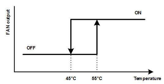
LimeSDR-Mini has integrated temperature sensor which controls FAN to keep board in operating temperature range. FAN must be connected to J10 (0.1” pitch) connector. FAN control voltage is 5V, but it can be changed to 3.3V by resistors. Fan will be turned on if board will heat up to 55°C and FAN will be turned off if board will cool down to 45°C. By default temperature sensor is unpopulated and FAN is always on.

Clock Distribution
TBD
Power Distribution
LimeSDR-Mini board is powered from USB port. LimeSDR-Mini board power delivery network consists of different power rails with different voltages, filters, power sequences. LimeSDR-Mini board power distribution block diagram is presented in Figure 9.