Getting Started with the LimeNET-Micro: Difference between revisions
| Line 41: | Line 41: | ||
=== Further reading === | === Further reading === | ||
* [[LimeNET-Micro_v2.1_hardware_description | LimeNET-Micro v2.1 hardware description]] | |||
* [https://www.raspberrypi.org/documentation/ Raspberry Pi documentation] - Raspberry Pi documentation database | |||
* [[LMS7002Mr3_Calibration_Using_MCU|LMS7002M (Mask 1) Transceiver Calibration]] - LMS7002Mr3 calibration guide, using internal MCU | |||
* [[LimeSDR Made Simple]] - Demystifying using SDR in the real world and programming a simple example with confidence, through bite sized chunks (note that not all examples will work with the Mini, e.g. those using the waveform player) | |||
* [https://github.com/myriadrf/LMS7002M-docs/blob/master/LMS7002M_Data_Sheet_v3.1r00.pdf LMS7002M Datasheet (PDF)] - LMS7002M RF transceiver datasheet | |||
* [https://github.com/myriadrf/LMS7002M-docs/blob/master/LMS7002M_Programming_and_Calibration_Guide_v31r05.pdf LMS7002M Programming and Calibration Guide (PDF)] - LMS7002M programming and calibration guide | |||
Revision as of 14:06, 3 April 2019
Getting Started with LimeNET-Micro
Basic setup
To get LimeNET-Micro board up and running:
- Select how the board will be powered by placing a jumper on J27 header;
- Connect mouse and keyboard to J10 USB connectors;
- Connect monitor cable to J19 HDMI connector;
- Insert CM3 module into J13 socket (or CM3(L) module into J13 and uSD card into J16 slot);
- Flash eMMC or uSD card;
- Install LimeSuite
Powering the board
LimeNET-Micro board can be powered in three ways:
- Power over Ethernet – using RJ45 connector and power sourcing equipment (PSE) such as PoE capable network switch or PoE injector. LimeNET-Micro board works with PSE supplying power in “Mode A/Endspan” as well in “Mode B/Midspan” modes;
- DC connector - 5V power source connected to J28 power jack should be capable to provide 2A-3A current;
- microUSB port - 5V power source connected to J15 connector should be capable to provide 2A-3A current;
Power source can be selected fitting jumper in one of the three positions on J27 header (see Figure 1):
- A (pins 5-6) – 5V micro USB;
- B (pins 3-4) – 5V external DC;
- C (pins 1-2) – Power over Ethernet;
Flashing eMMC or uSD card
To flash eMMC or uSD card with latest Raspbian image please follow these steps:
- Download Raspbian image file by following this [link].
- Choose how the board will be powered by mounting a jumper on J27 header.
- Mount “USB boot”(J14) and unmount "EXT USB"(J18) jumpers.
- Insert CM3 module into J13 socket (or CM3(L) module into J13 and uSD card into J16 slot).
- Flash Raspbian image by following this guide [link].
- Remove “USB boot”(J14) jumper and reapply power. LimeNET-Micro should now boot to newly installed Raspbian image.
Installing Lime Suite
After booting to the latest Raspbian image you can install LimeSuite by following the instructions on Getting Started with Lime Suite
FPGA programming
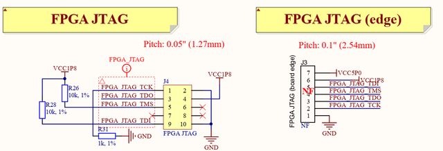
Intel MAX10 FPGA can be programmed using JTAG adapter such as Intel FPGA USB Download Cable (formerly known as Altera USB-Blaster download cable). LimeNET-Micro board has two different size and pin count JTAG headers (J4 - 10pin 0.05” pitch header and J3 - 7pin 0.1” pitch edge connector). Additional cable adapter is needed to connect download cable to LimeNET-Micro board because Intel FPGA USB Download Cable comes with 10-pin, 0.1” pitch female connector.

Further reading
- LimeNET-Micro v2.1 hardware description
- Raspberry Pi documentation - Raspberry Pi documentation database
- LMS7002M (Mask 1) Transceiver Calibration - LMS7002Mr3 calibration guide, using internal MCU
- LimeSDR Made Simple - Demystifying using SDR in the real world and programming a simple example with confidence, through bite sized chunks (note that not all examples will work with the Mini, e.g. those using the waveform player)
- LMS7002M Datasheet (PDF) - LMS7002M RF transceiver datasheet
- LMS7002M Programming and Calibration Guide (PDF) - LMS7002M programming and calibration guide