Uploads by Ghalfacree
Jump to navigation
Jump to search
This special page shows all uploaded files.
| Date | Name | Thumbnail | Size | Description | Versions |
|---|---|---|---|---|---|
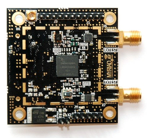
| 14:42, 13 July 2015 | Myriadrf1-1.jpg (file) |  |
137 KB | Myriad-RF 1 board, initial image. | 1 |
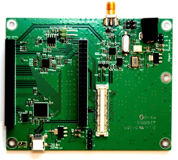
| 14:53, 13 July 2015 | DE0-Nano-Interface-Board-1.jpg (file) |  |
157 KB | The Digital Interface Board for connecting the DE0-Nano FPGA Development System to the Myriad-RF 1. | 1 |
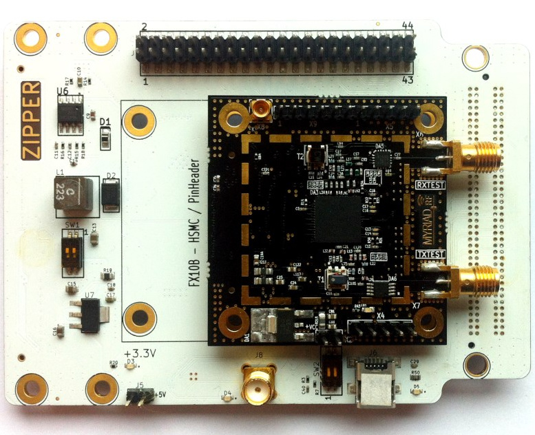
| 14:55, 13 July 2015 | Zipper-1.jpg (file) |  |
217 KB | Zipper Interface Board with Myriad-RF 1 installed. | 1 |
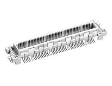
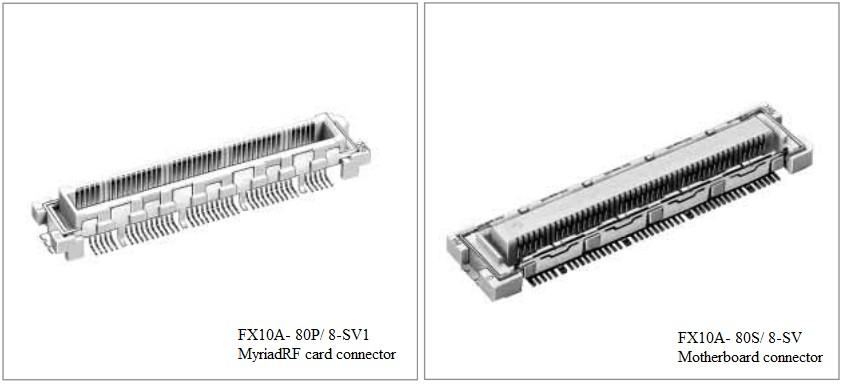
| 14:57, 13 July 2015 | RFDIO-Card-Connector-1.jpg (file) |  |
16 KB | The card-side Hirose connector for the RFDIO interface. | 1 |
| 15:49, 13 July 2015 | DE0-Nano-1.jpg (file) |  |
74 KB | DE0-Nano FPGA Development System. | 1 |
| 15:50, 13 July 2015 | DE0interfaceboard-Assembled-1.jpg (file) |  |
57 KB | DE0-Nano Interface Board, assembled with DE0-Nano and Myriad-RF1. | 1 |
| 16:03, 13 July 2015 | Zipper-Block-Diagram.jpg (file) |  |
126 KB | Block diagram for the Zipper Interface Board. | 1 |
| 16:04, 13 July 2015 | Myriad-RF-1-Block-Diagram.jpg (file) |  |
101 KB | Block diagram for the Myriad-RF 1. | 1 |
| 12:31, 16 July 2015 | RFDIO-Figure1.jpg (file) |  |
29 KB | Figure 1 from the RFDIO Connector Specification, Revision 1.0.1. | 1 |
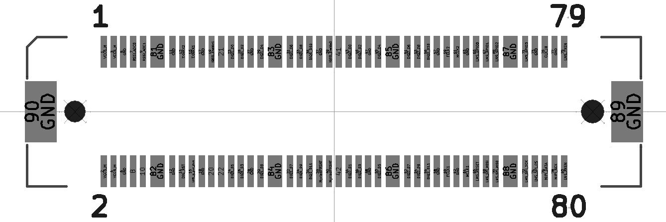
| 12:34, 16 July 2015 | RFDIO-Figure2.jpg (file) |  |
56 KB | Figure 2 from the RFDIO Connector Specification, Revision 1.0.1. | 1 |
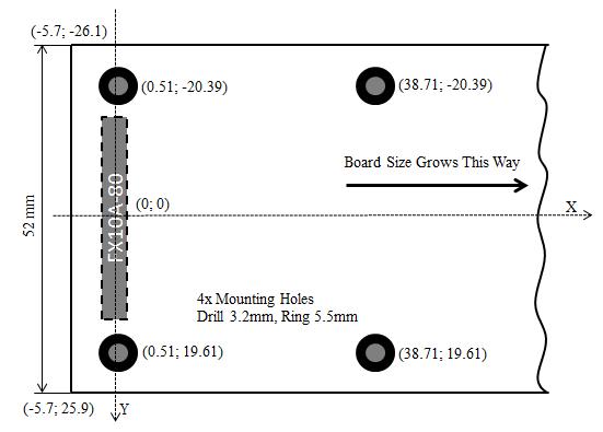
| 12:37, 16 July 2015 | RFDIO-Figure3.jpg (file) |  |
24 KB | Figure 3 from the RFDIO Connector Specification, Revision 1.0.1. | 1 |
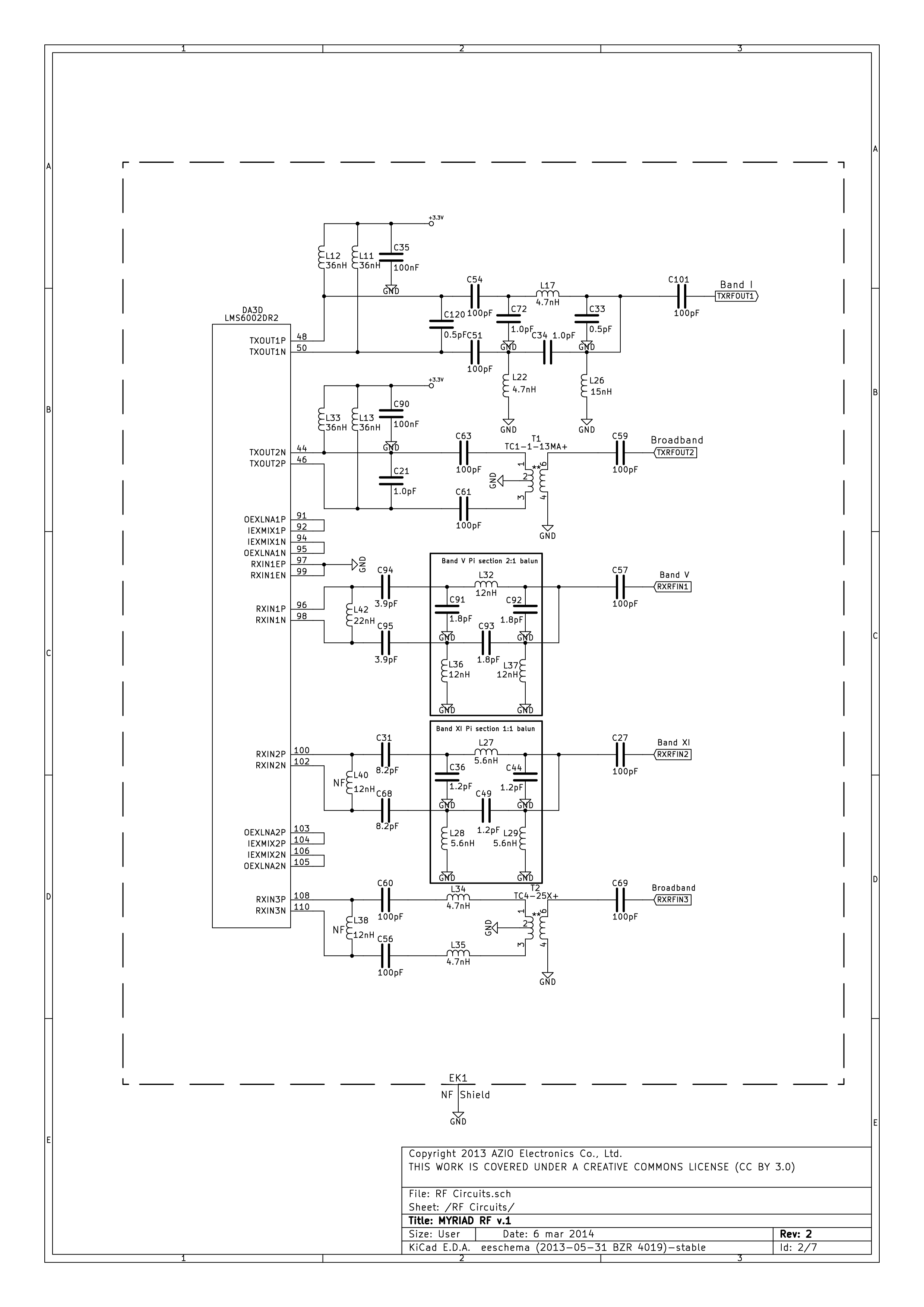
| 13:30, 16 July 2015 | MyriadRF-Schematics-1.png (file) |  |
168 KB | Myriad-RF 1 Schematic Sheet 1, RF Circuits, v.1. | 1 |
| 13:32, 16 July 2015 | MyriadRF-Schematics-2.png (file) |  |
113 KB | Myriad-RF 1 Schematics Sheet 2, Analogue Circuits. | 1 |
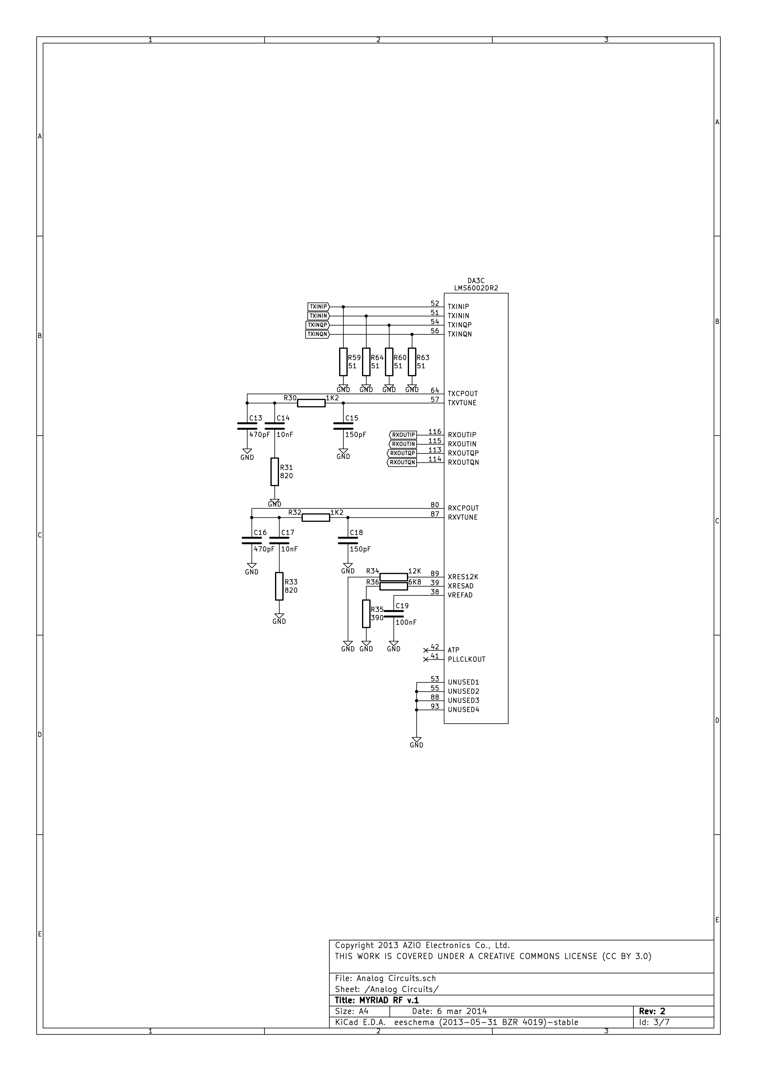
| 13:33, 16 July 2015 | MyriadRF-Schematics-3.png (file) |  |
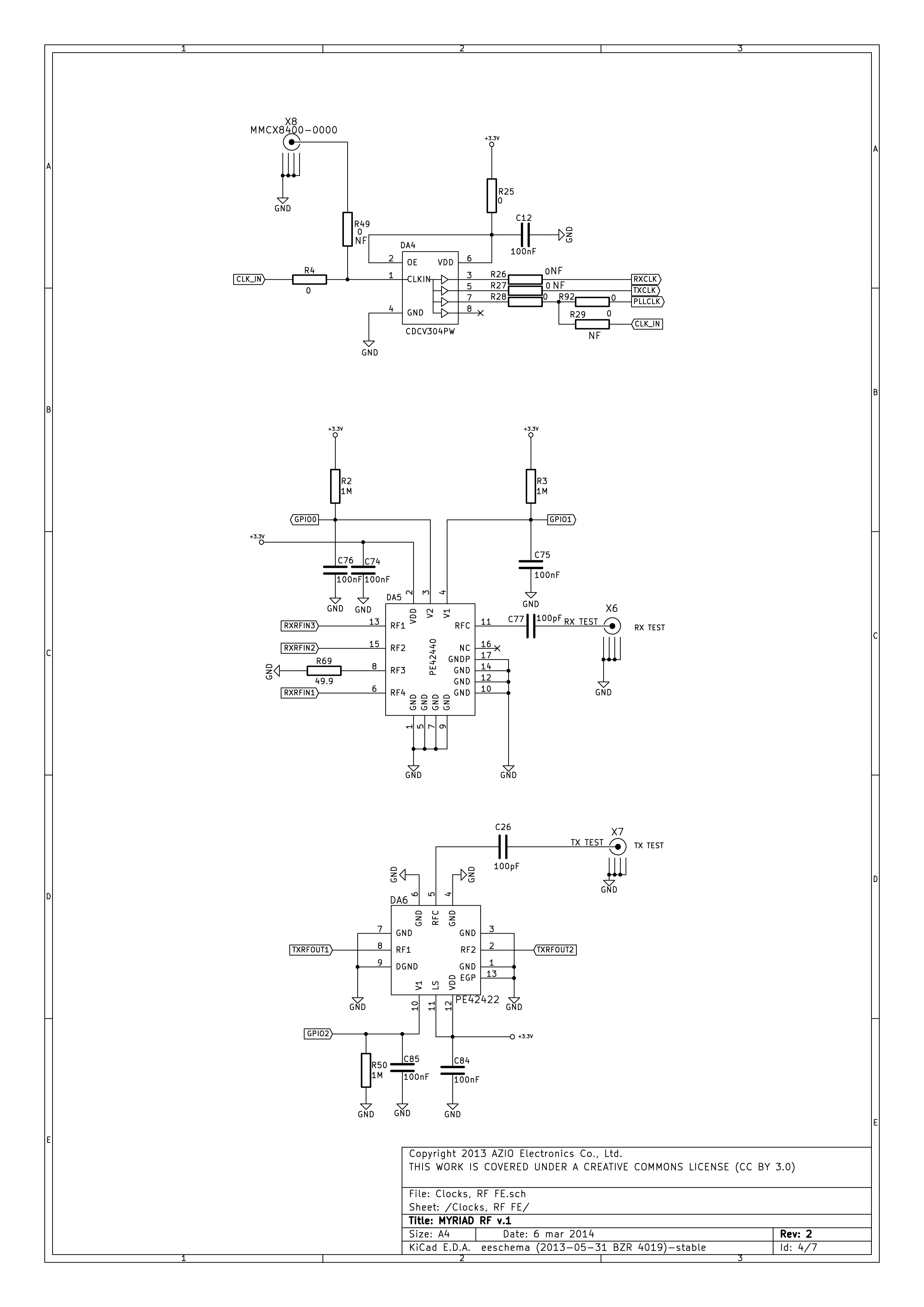
139 KB | Myriad-RF 1 Schematics Sheet 3, Clocks, RF FE. | 1 |
| 13:34, 16 July 2015 | MyriadRF-Schematics-4.png (file) |  |
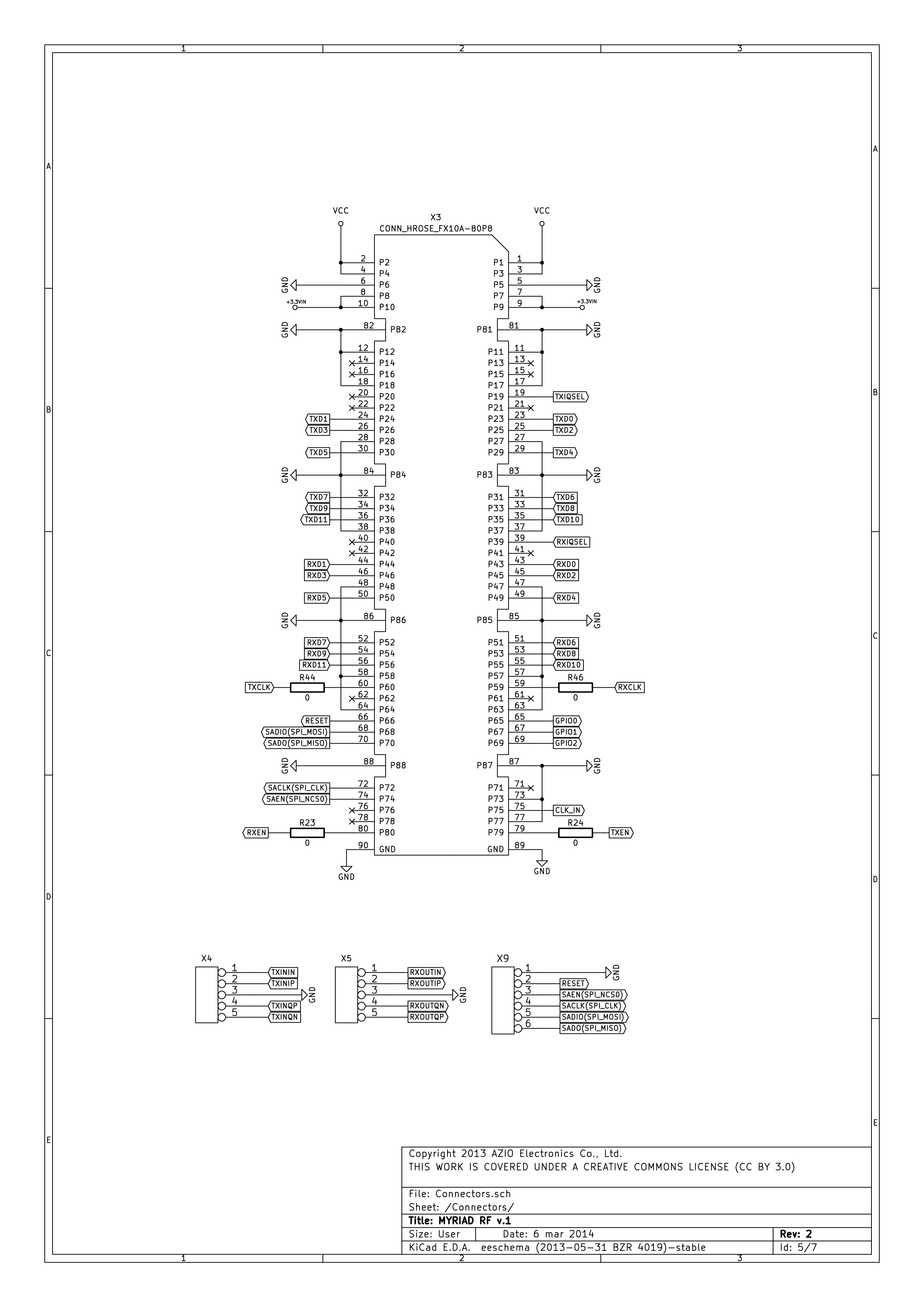
189 KB | Myriad-RF 1 Schematics Sheet 4, Connectors. | 1 |
| 13:35, 16 July 2015 | MyriadRF-Schematics-5.png (file) |  |
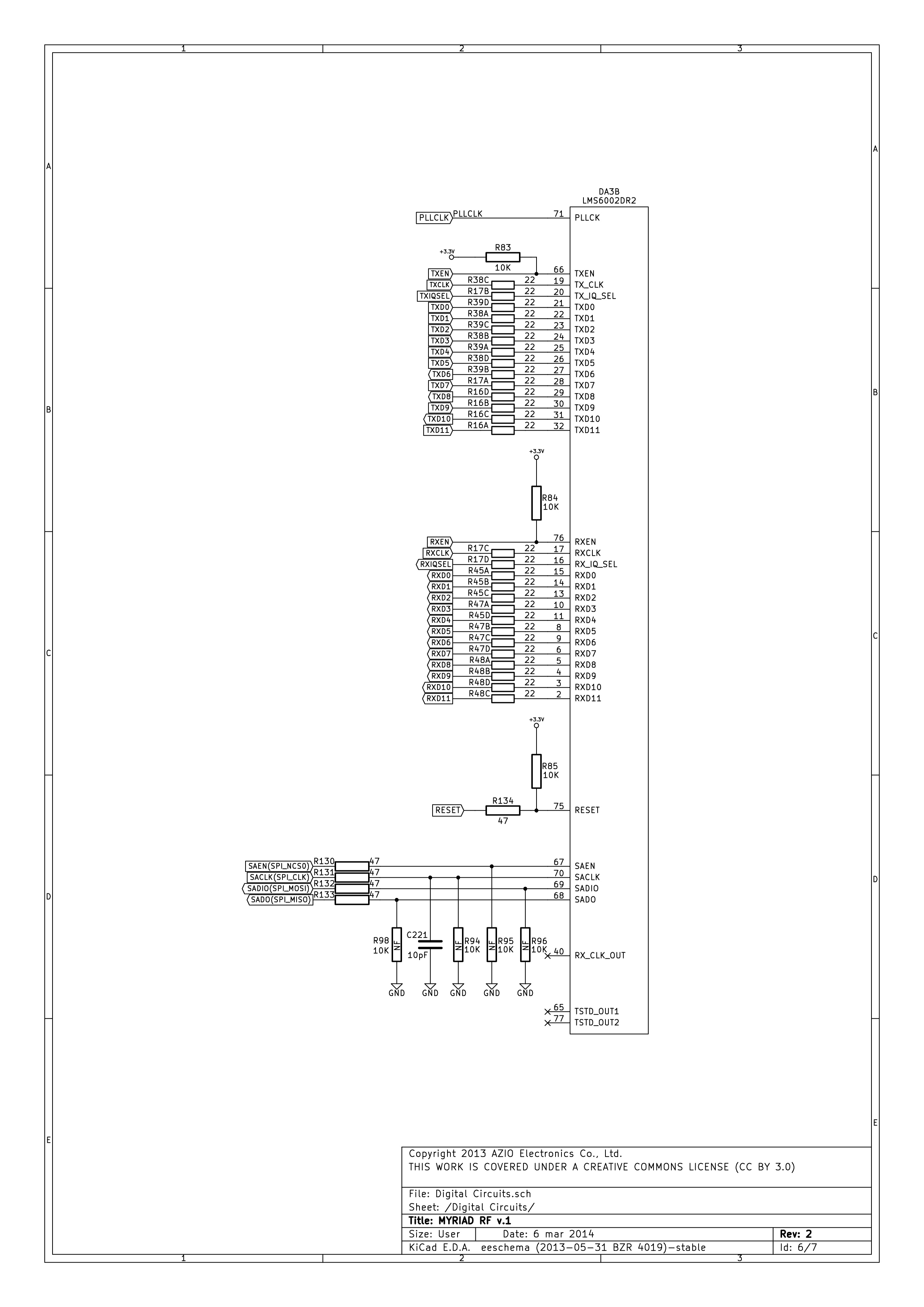
173 KB | Myriad-RF 1 Schematics Sheet 5, Digital Circuits. | 1 |
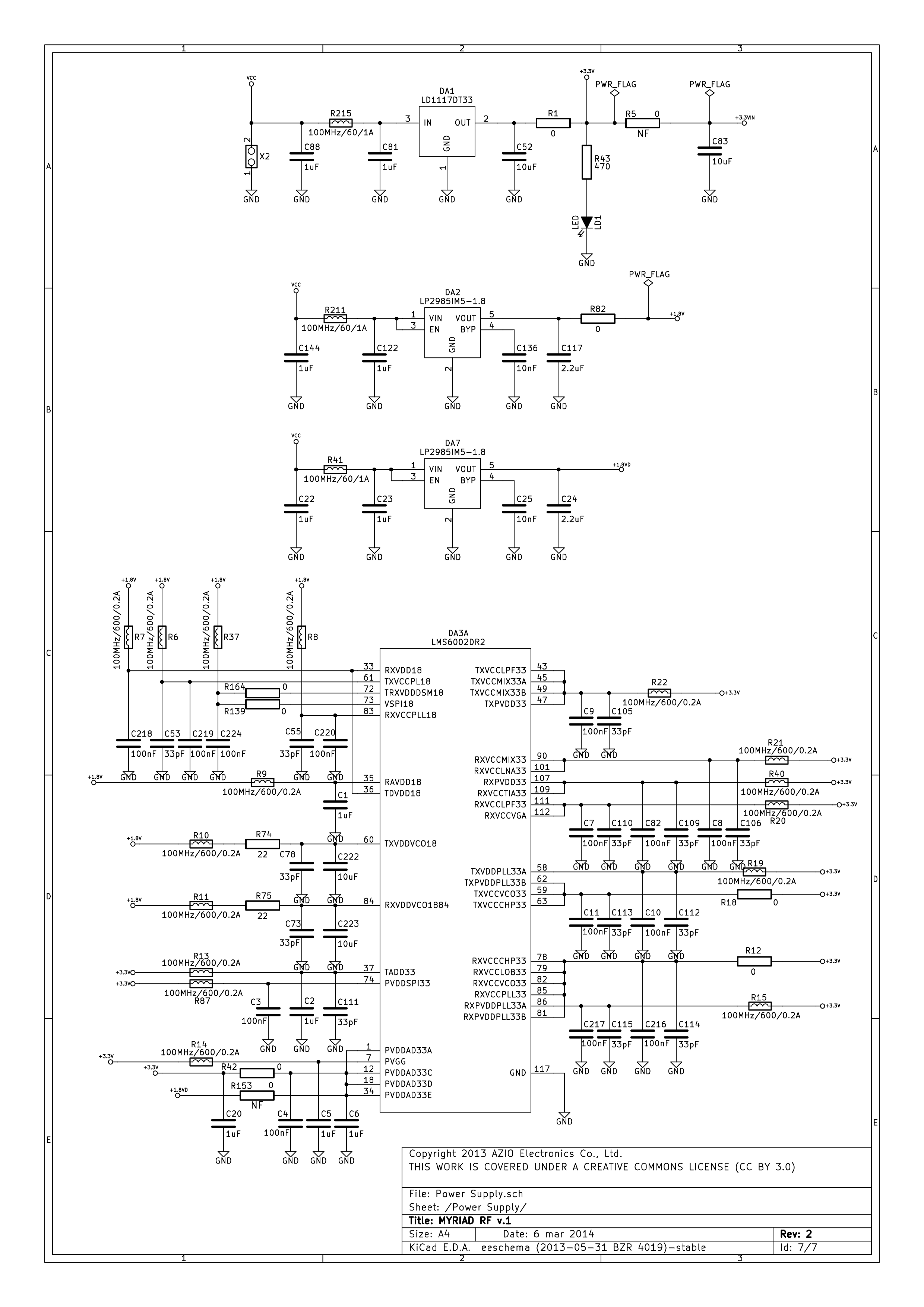
| 13:35, 16 July 2015 | MyriadRF-Schematics-6.png (file) |  |
242 KB | Myriad-RF 1 Schematics Sheet 6, Power Supply. | 1 |
| 13:41, 16 July 2015 | DE0-Nano-Interface-Board-Schematics-1.png (file) |  |
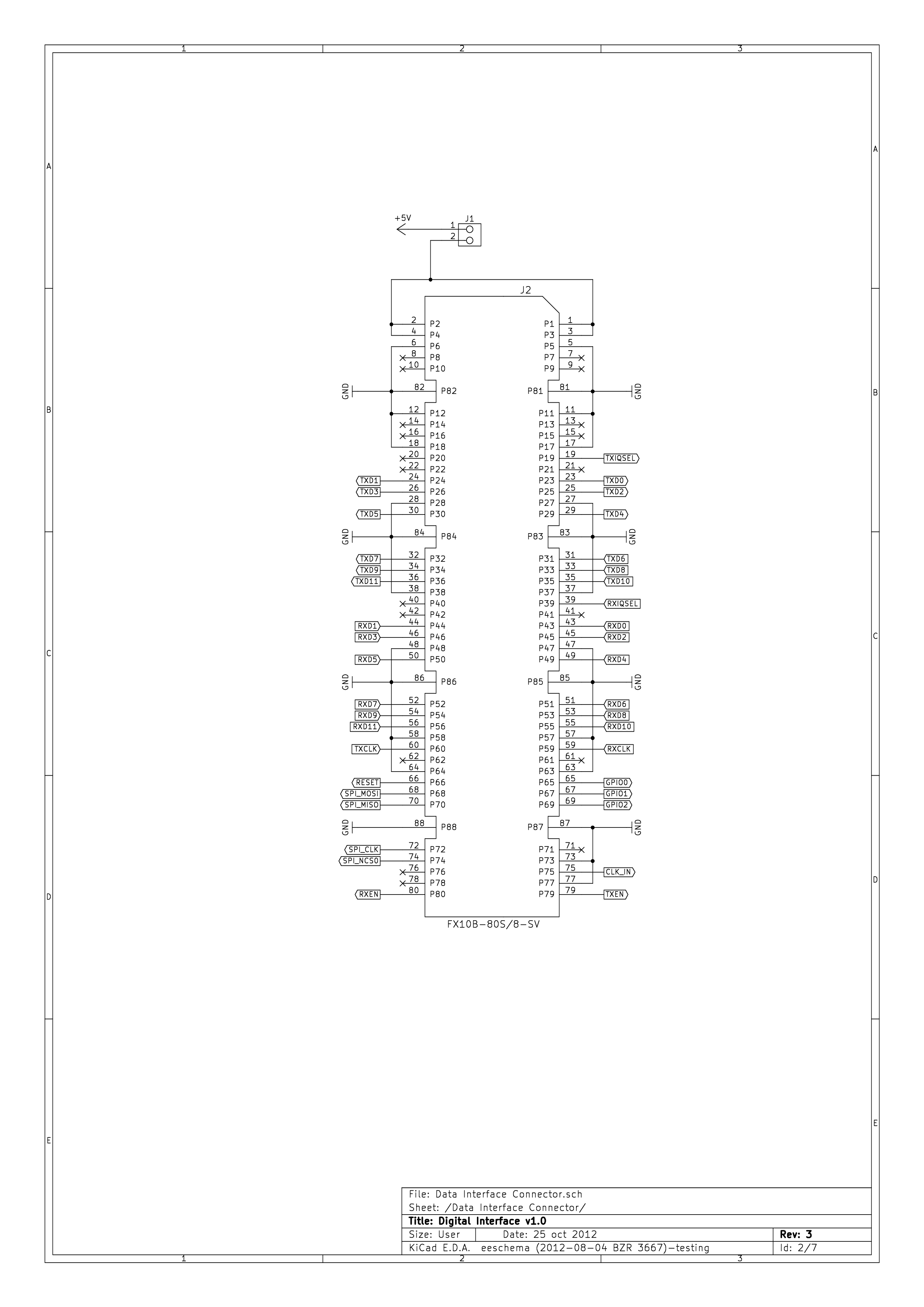
144 KB | DE0-Nano Interface Board Schematic Sheet 1, Data Interface Connector. | 1 |
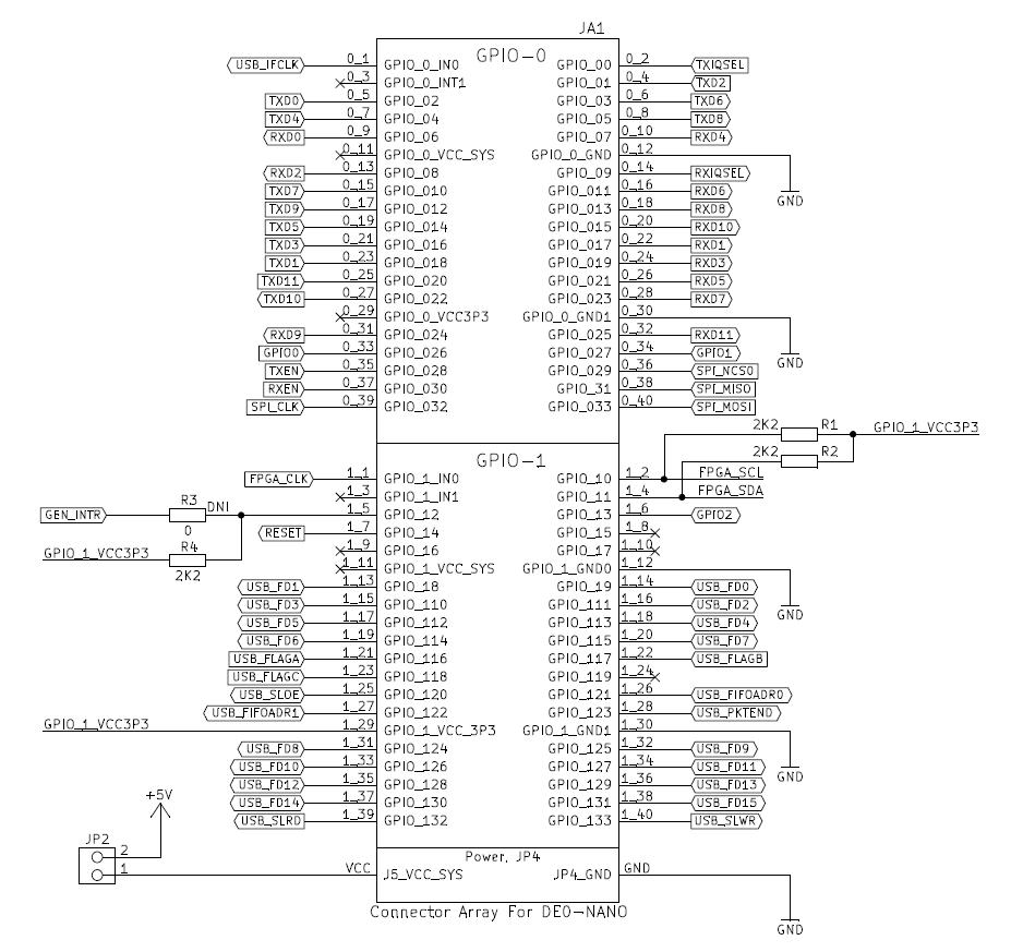
| 13:41, 16 July 2015 | DE0-Nano-Interface-Board-Schematics-2.png (file) |  |
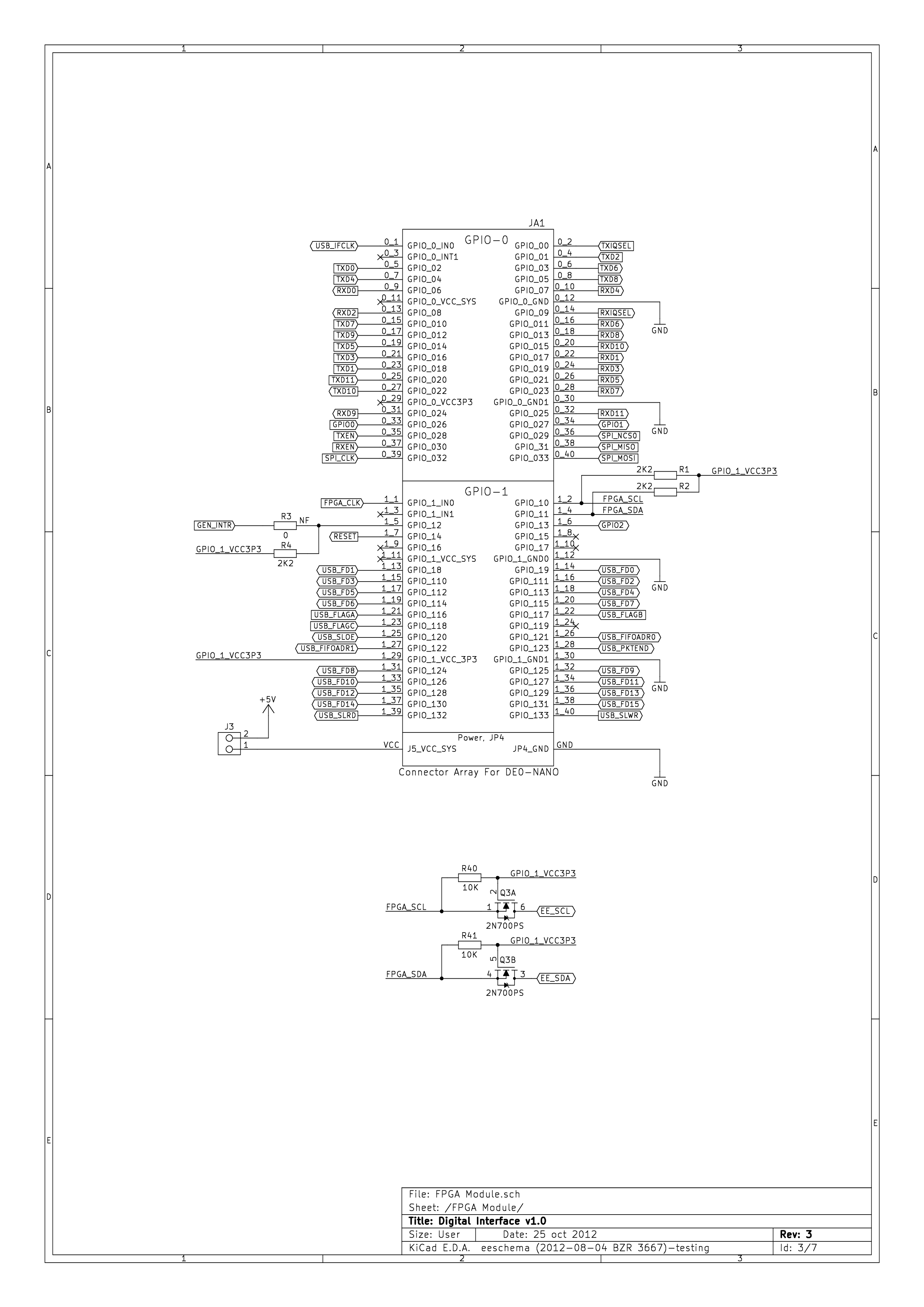
222 KB | DE0-Nano Interface Board Schematic Sheet 2, FPGA Module. | 1 |
| 13:42, 16 July 2015 | DE0-Nano-Interface-Board-Schematics-3.png (file) |  |
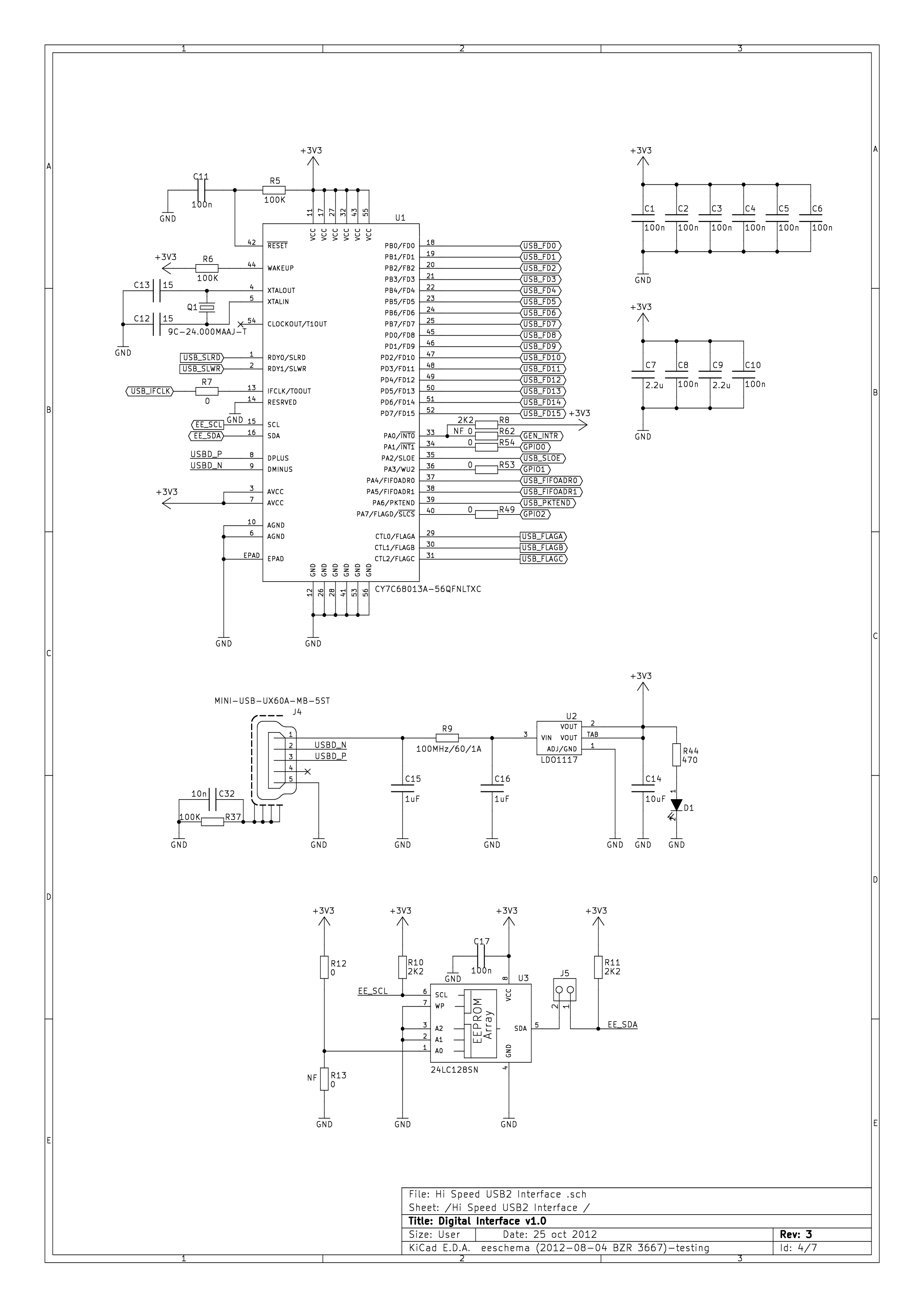
194 KB | DE0-Nano Interface Board Schematic Sheet 3, Hi-Speed USB 2.0 Interface. | 1 |
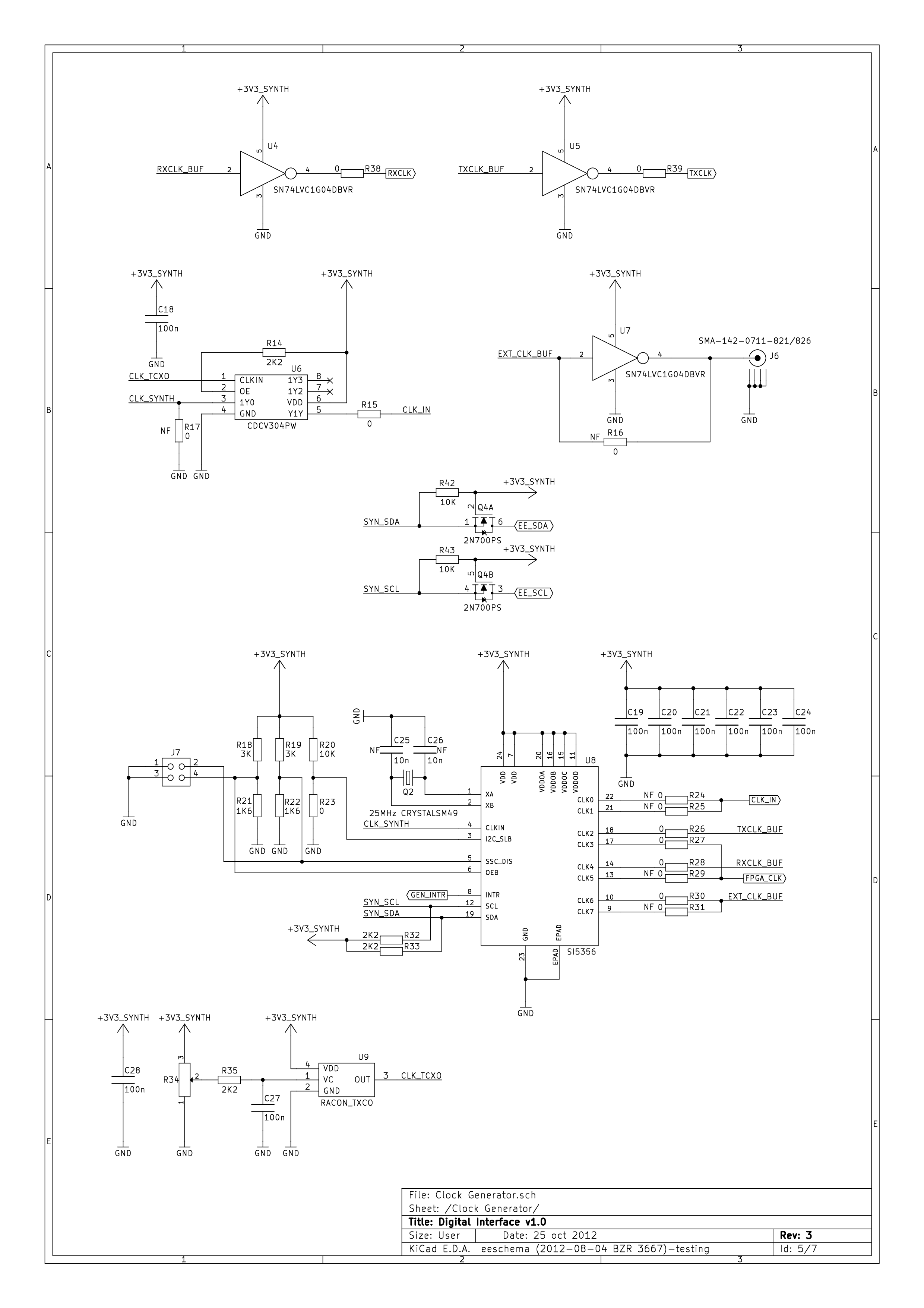
| 13:42, 16 July 2015 | DE0-Nano-Interface-Board-Schematics-4.png (file) |  |
171 KB | DE0-Nano Interface Board Schematic Sheet 4, Clock Generator. | 1 |
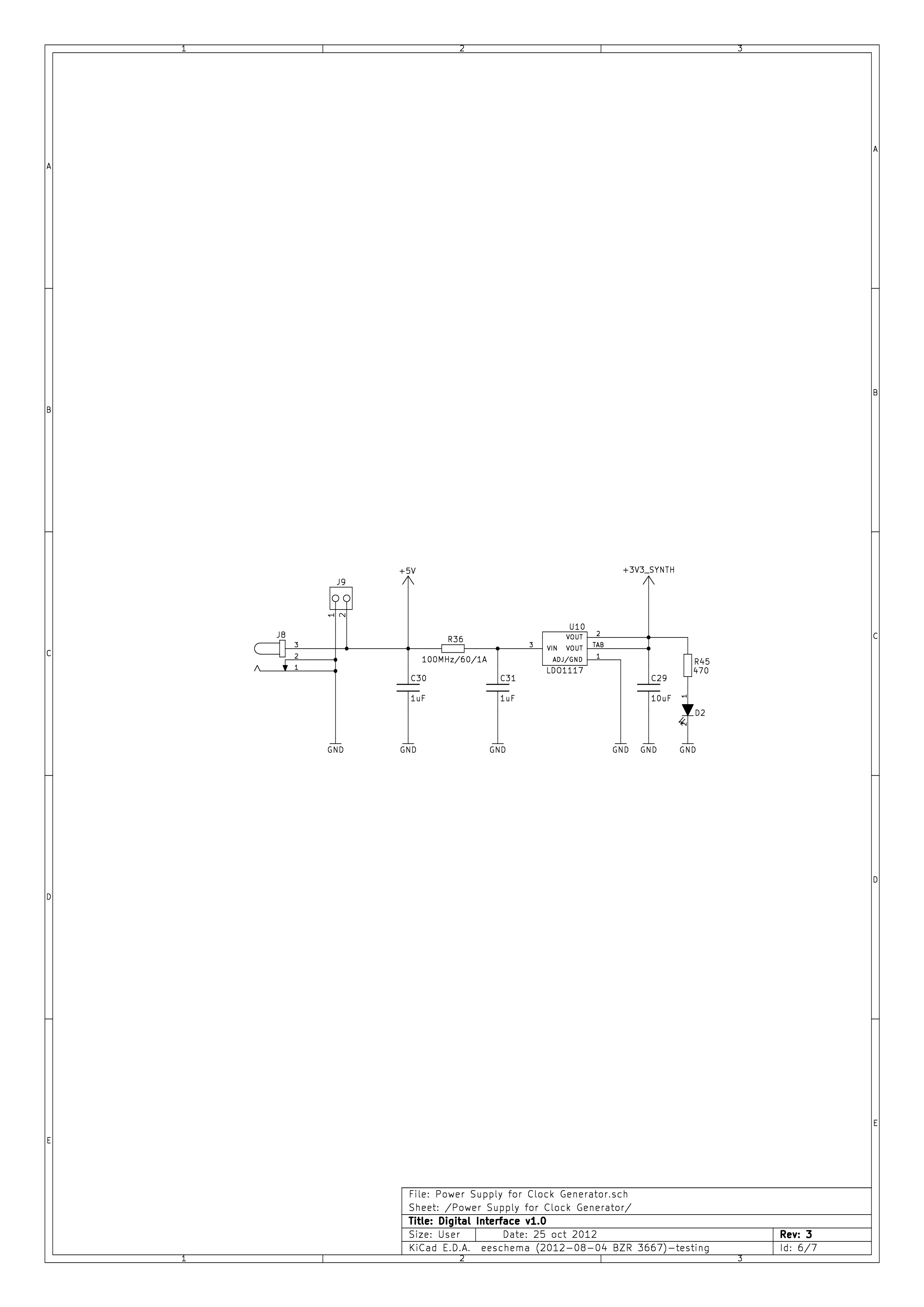
| 13:43, 16 July 2015 | DE0-Nano-Interface-Board-Schematics-5.png (file) |  |
65 KB | DE0-Nano Interface Board Schematic Sheet 5, Power Supply for Clock Generator. | 1 |
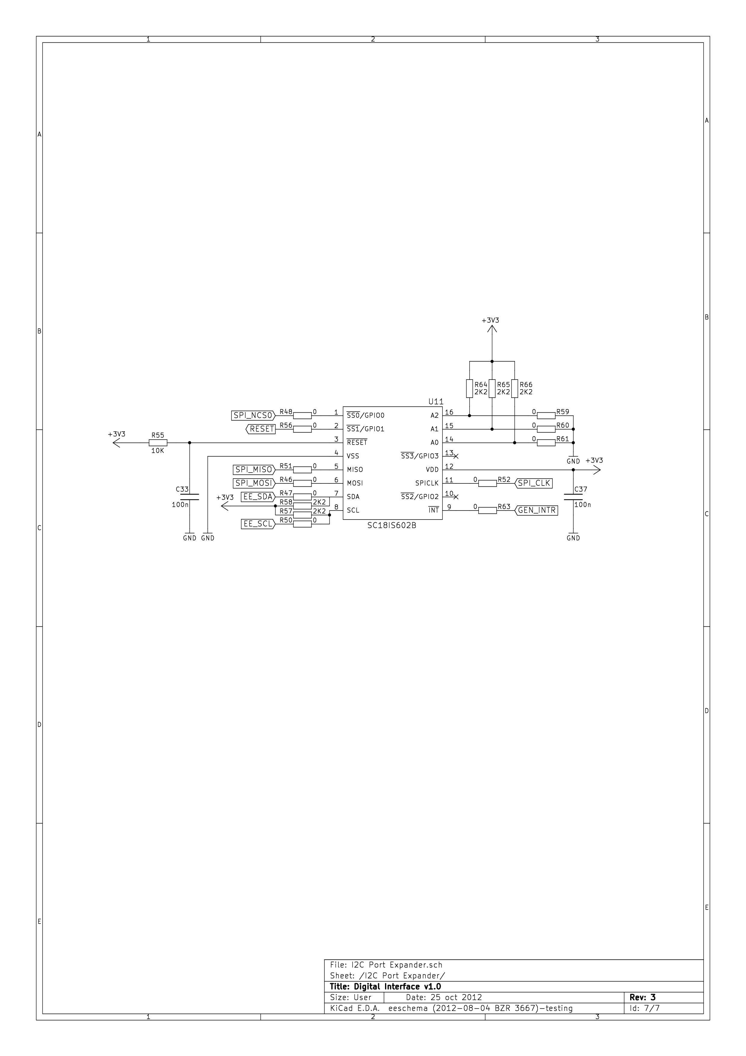
| 13:43, 16 July 2015 | DE0-Nano-Interface-Board-Schematics-6.png (file) |  |
88 KB | DE0-Nano Interface Board Schematic Sheet 6, I²C Port Expander. | 1 |
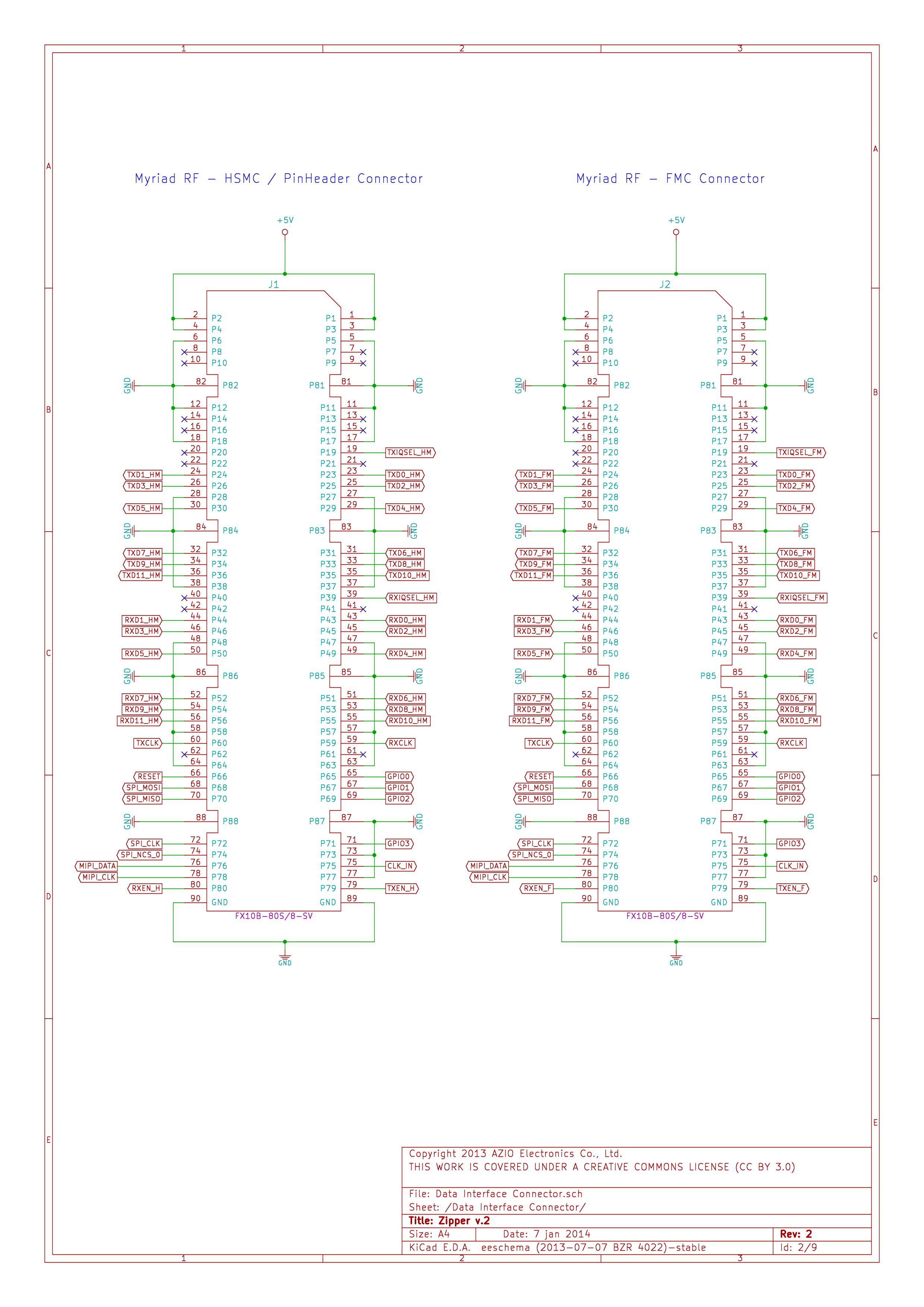
| 13:47, 16 July 2015 | Zipper-Interface-Board-Schematics-1.png (file) |  |
255 KB | Zipper Interface Board Schematic Sheet 1, Data Interface Connector. | 1 |
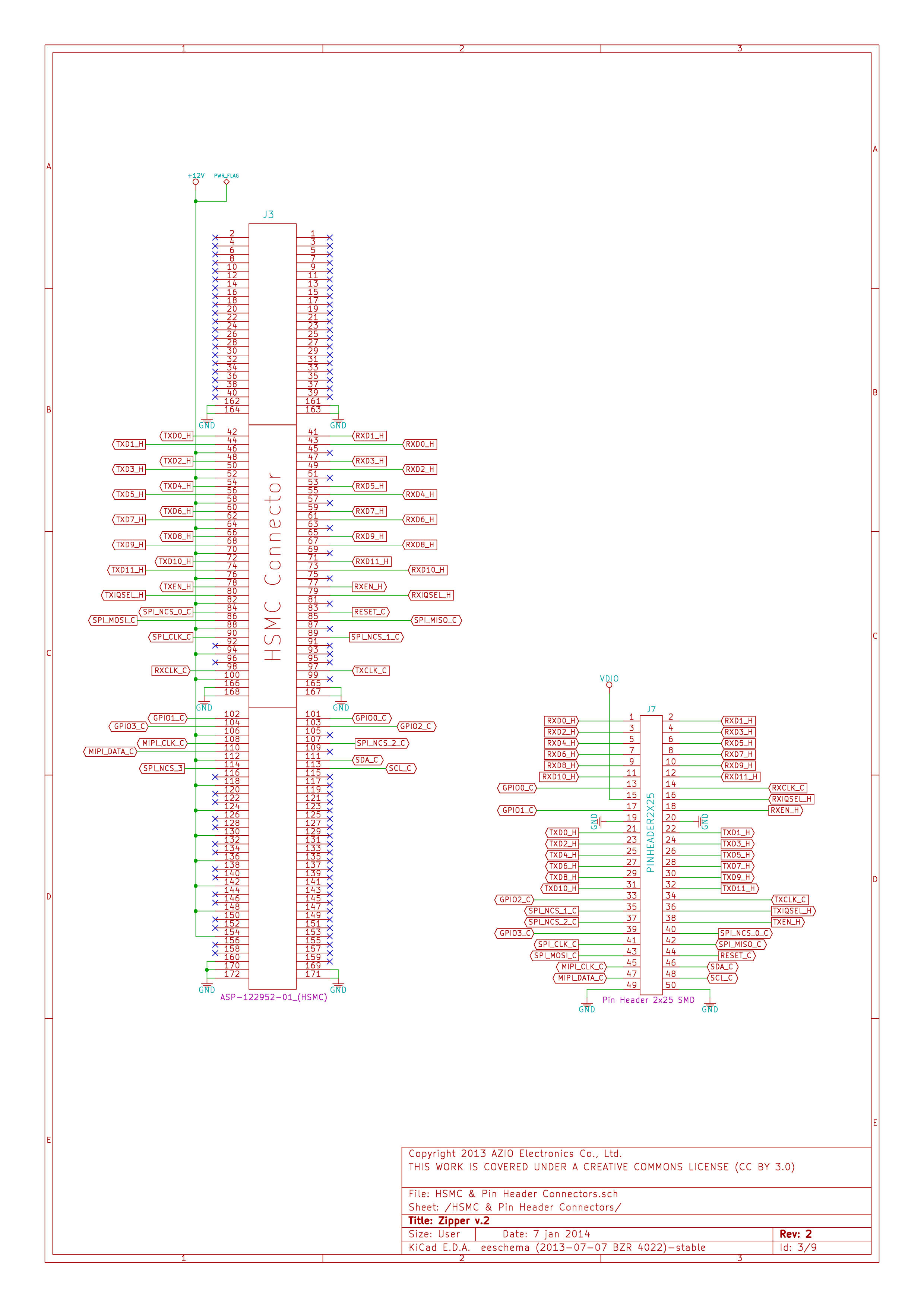
| 13:47, 16 July 2015 | Zipper-Interface-Board-Schematics-2.png (file) |  |
326 KB | Zipper Interface Board Schematic Sheet 2, HSMC & Pin Header Connectors. | 1 |
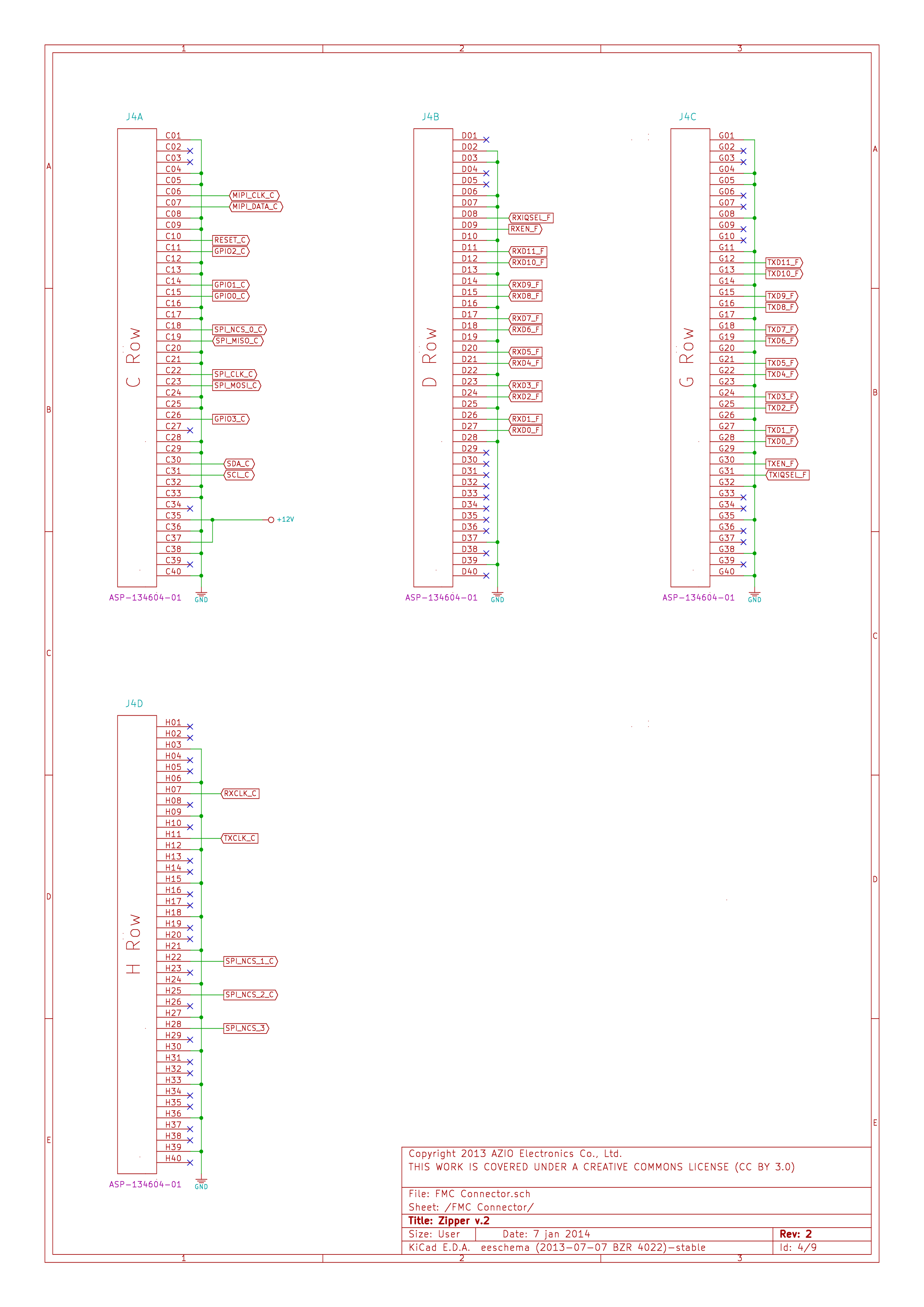
| 13:48, 16 July 2015 | Zipper-Interface-Board-Schematics-3.png (file) |  |
256 KB | Zipper Interface Board Schematic Sheet 3, FMC Connector. | 1 |
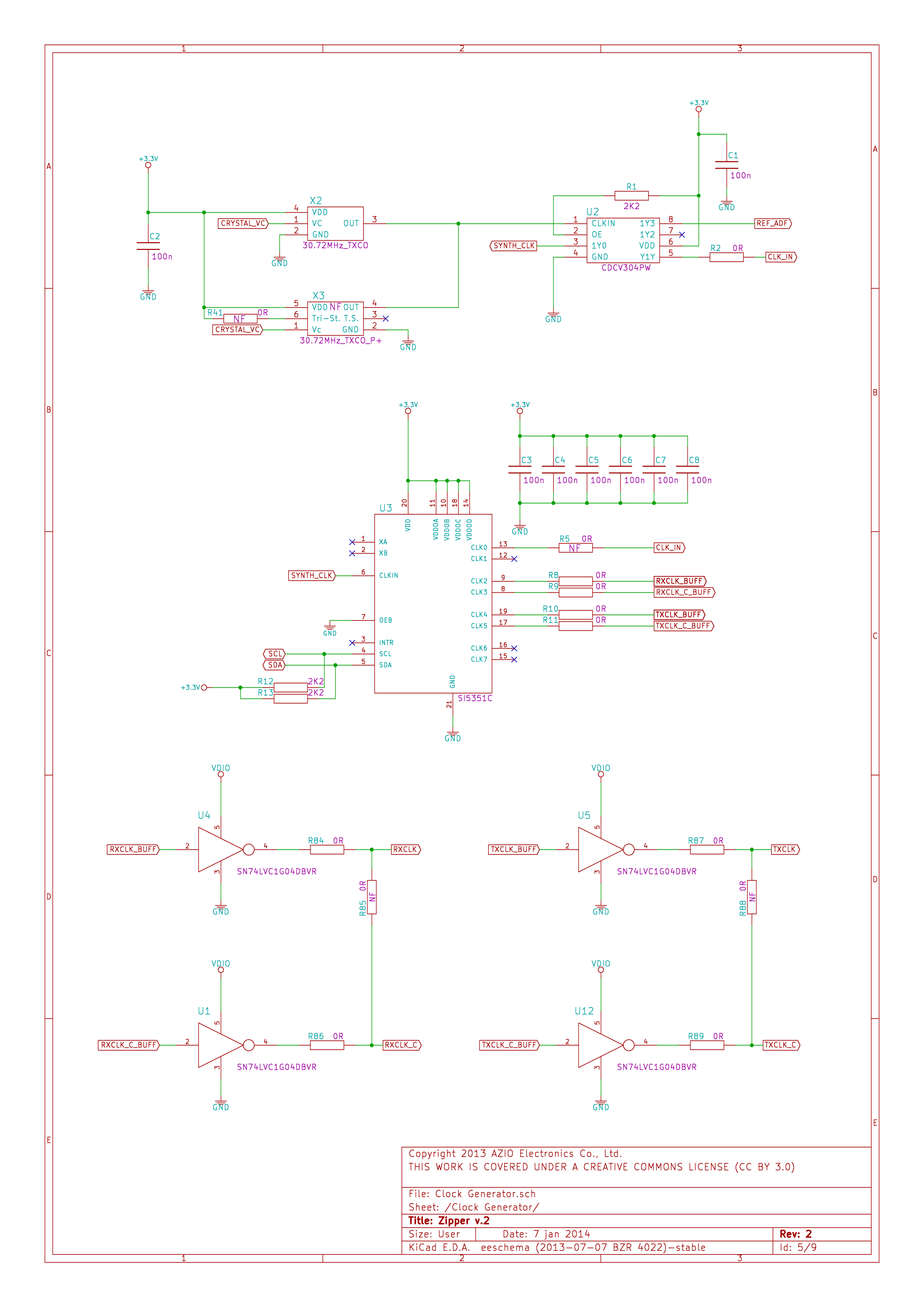
| 13:48, 16 July 2015 | Zipper-Interface-Board-Schematics-4.png (file) |  |
207 KB | Zipper Interface Board Schematic Sheet 4, Clock Generator. | 1 |
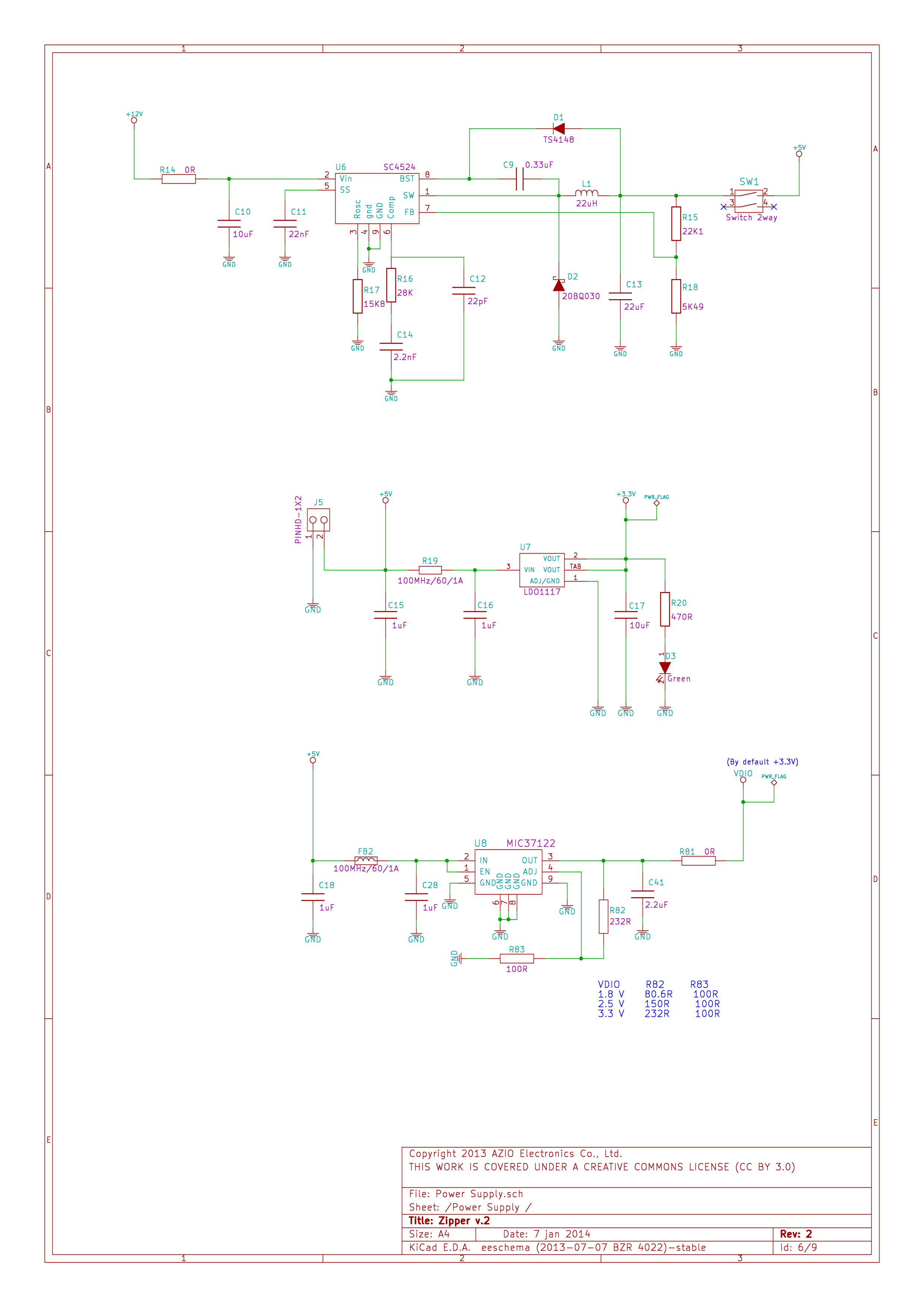
| 13:49, 16 July 2015 | Zipper-Interface-Board-Schematics-5.png (file) |  |
181 KB | Zipper Interface Board Schematic Sheet 5, Power Supply. | 1 |
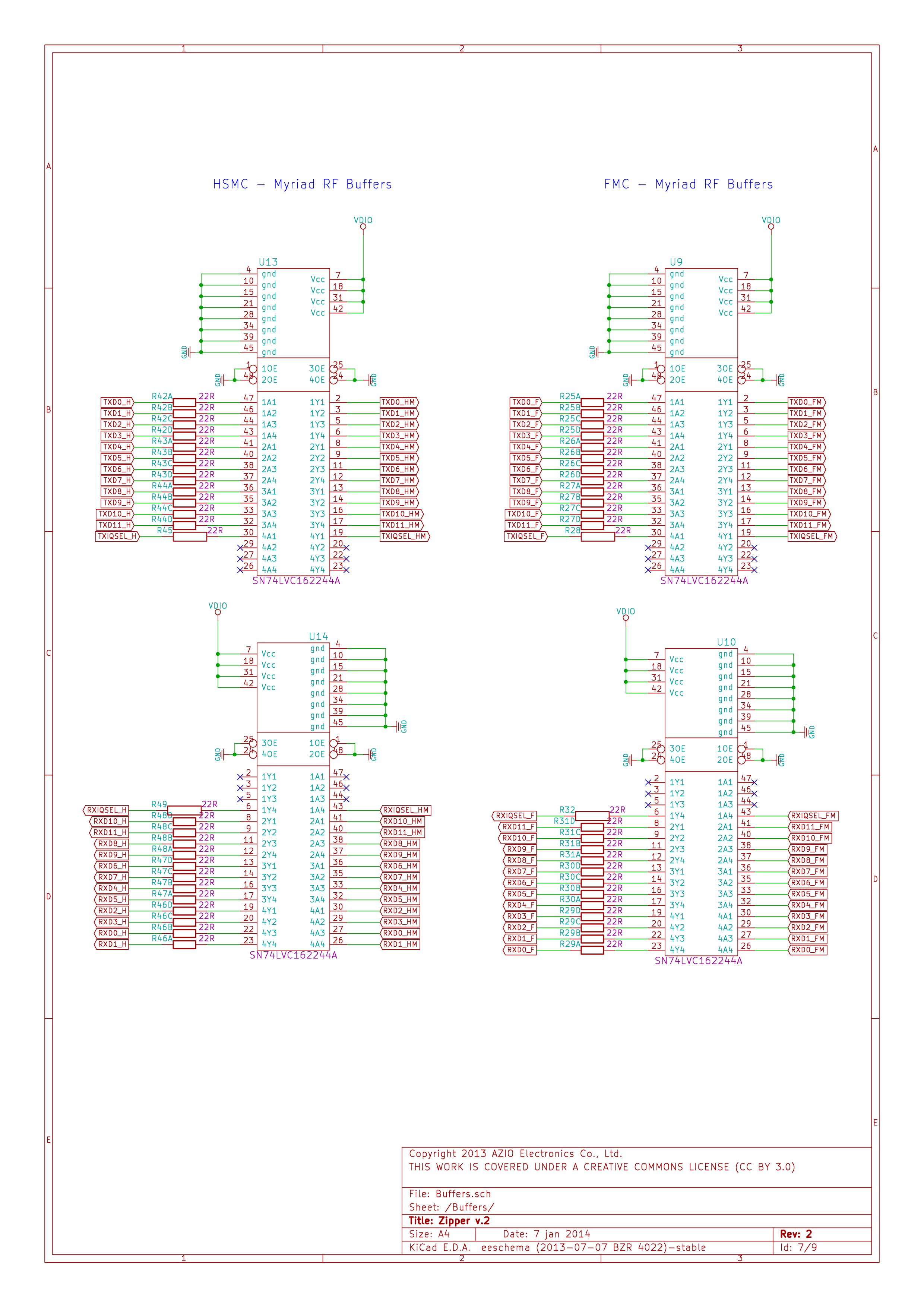
| 13:49, 16 July 2015 | Zipper-Interface-Board-Schematics-6.png (file) |  |
393 KB | Zipper Interface Board Schematic Sheet 6, Buffers. | 1 |
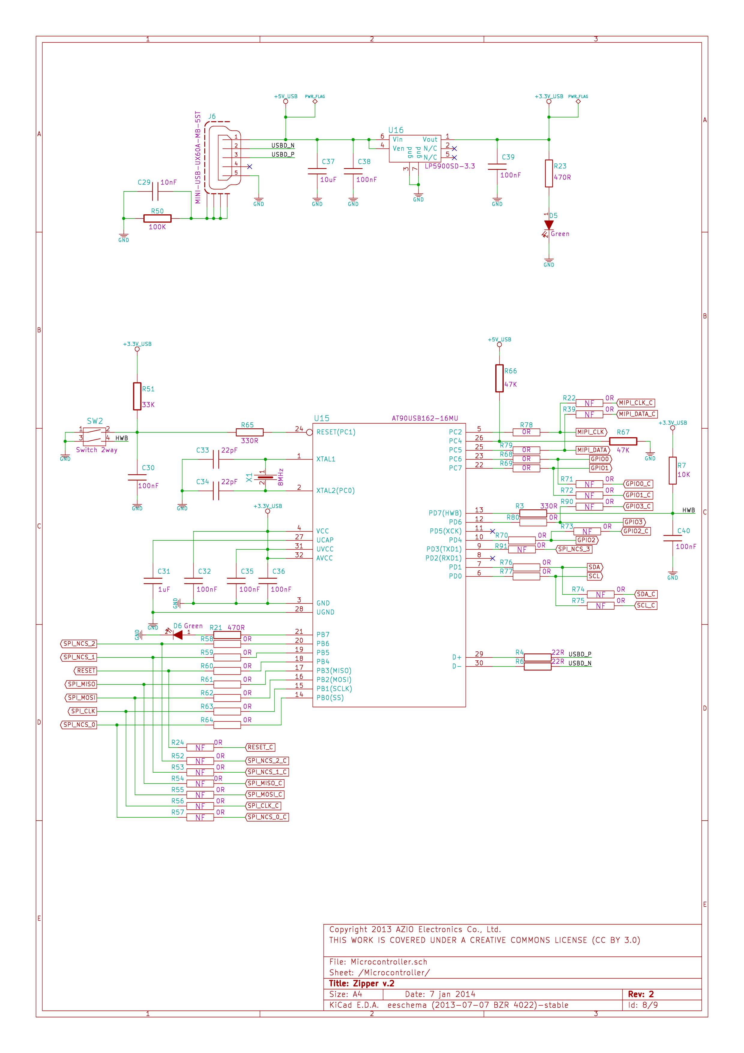
| 13:50, 16 July 2015 | Zipper-Interface-Board-Schematics-7.png (file) |  |
288 KB | Zipper Interface Board Schematic Sheet 7, Microcontroller. | 1 |
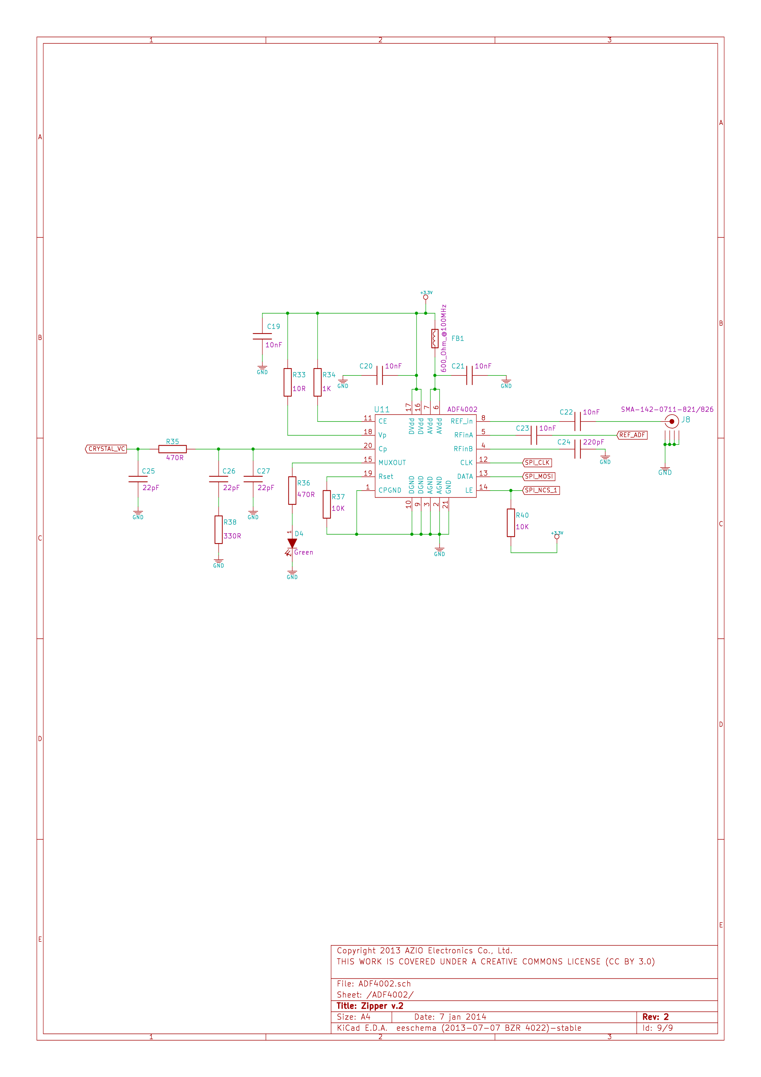
| 13:50, 16 July 2015 | Zipper-Interface-Board-Schematics-8.png (file) |  |
143 KB | Zipper Interface Board Schematic Sheet 8, ADF4002. | 1 |
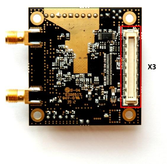
| 14:51, 16 July 2015 | MyriadRF1-Connectors-Top.jpg (file) |  |
42 KB | Myriad-RF 1 Board, with connectors labelled - top side. | 1 |
| 14:51, 16 July 2015 | MyriadRF1-Connectors-Bottom.jpg (file) |  |
47 KB | Myriad-RF 1 Board with connectors labelled - bottom side. | 1 |
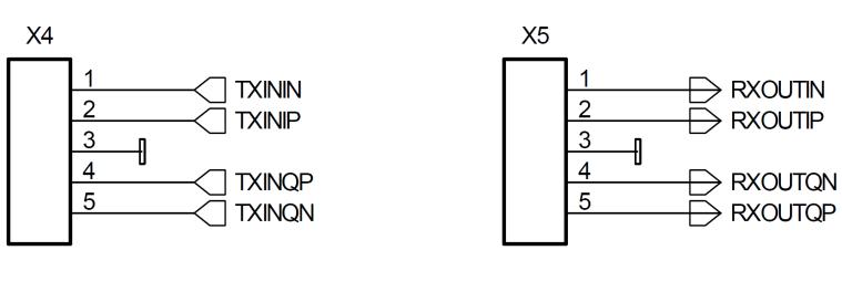
| 14:53, 16 July 2015 | MyriadRF1-X4-X5.jpg (file) |  |
19 KB | Myriad-RF 1 Board X4 and X5 connector pin-outs. | 1 |
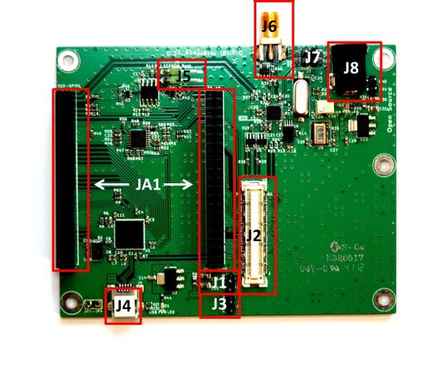
| 15:04, 16 July 2015 | DE0-Nano-Connections.jpg (file) |  |
54 KB | DE0-Nano Interface Board with connections labelled. | 1 |
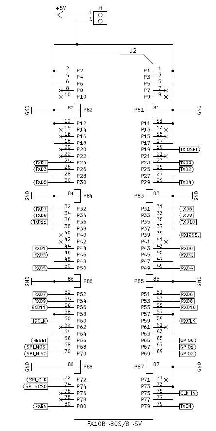
| 15:35, 16 July 2015 | DE0-Nano-J2.jpg (file) |  |
61 KB | DE0-Nano J2 connector pin-out. | 1 |
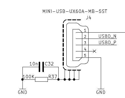
| 15:37, 16 July 2015 | DE0-Nano-J4.jpg (file) |  |
15 KB | DE0-Nano Interface Board J4, mini-USB connector. | 1 |
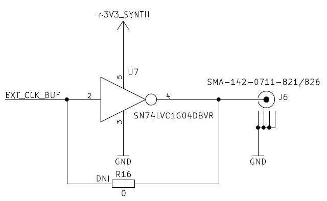
| 15:39, 16 July 2015 | DE0-Nano-J6.jpg (file) |  |
18 KB | DE0-Nano Interface Board J6 | 1 |
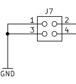
| 15:41, 16 July 2015 | DE0-Nano-J7.jpg (file) |  |
6 KB | DE0-Nano Interface Board J7. | 1 |
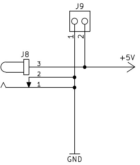
| 15:42, 16 July 2015 | DE0-Nano-J8-J9.jpg (file) |  |
12 KB | DE0-Nano Interface Board J8 and J9. | 1 |
| 15:44, 16 July 2015 | DE0-Nano-JA1.jpg (file) |  |
127 KB | DE0-Nano Interface Board JA1. | 1 |
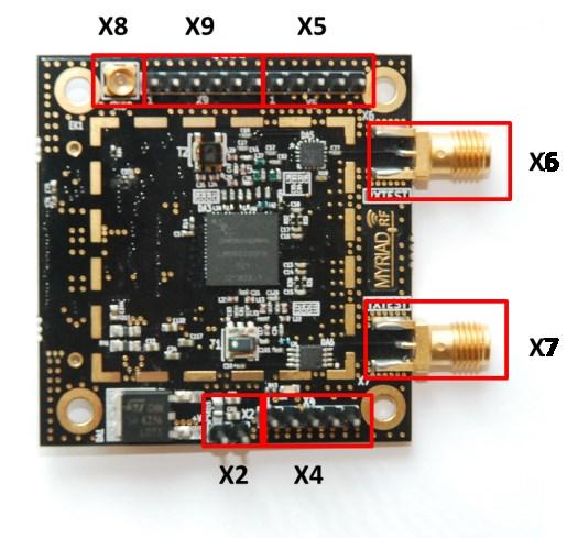
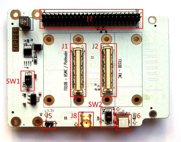
| 15:58, 16 July 2015 | Zipper-Connections-Top.jpg (file) |  |
66 KB | Zipper connections labelled, top side. | 1 |
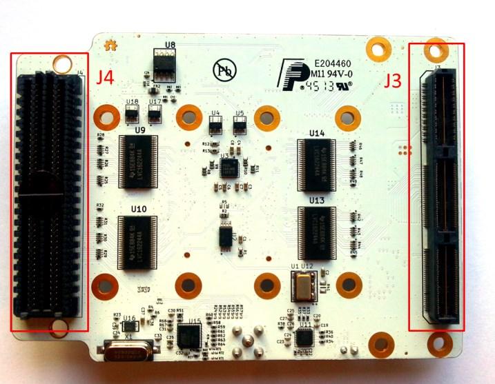
| 15:59, 16 July 2015 | Zipper-Connections-Bottom.jpg (file) |  |
68 KB | Zipper connections labelled, bottom side. | 1 |
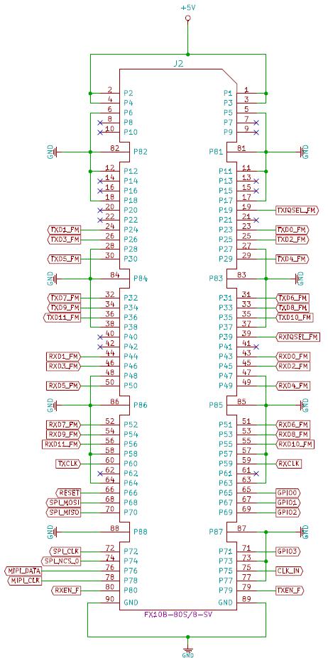
| 16:13, 16 July 2015 | Zipper-J2.jpg (file) |  |
71 KB | Zipper J2 connector. | 1 |
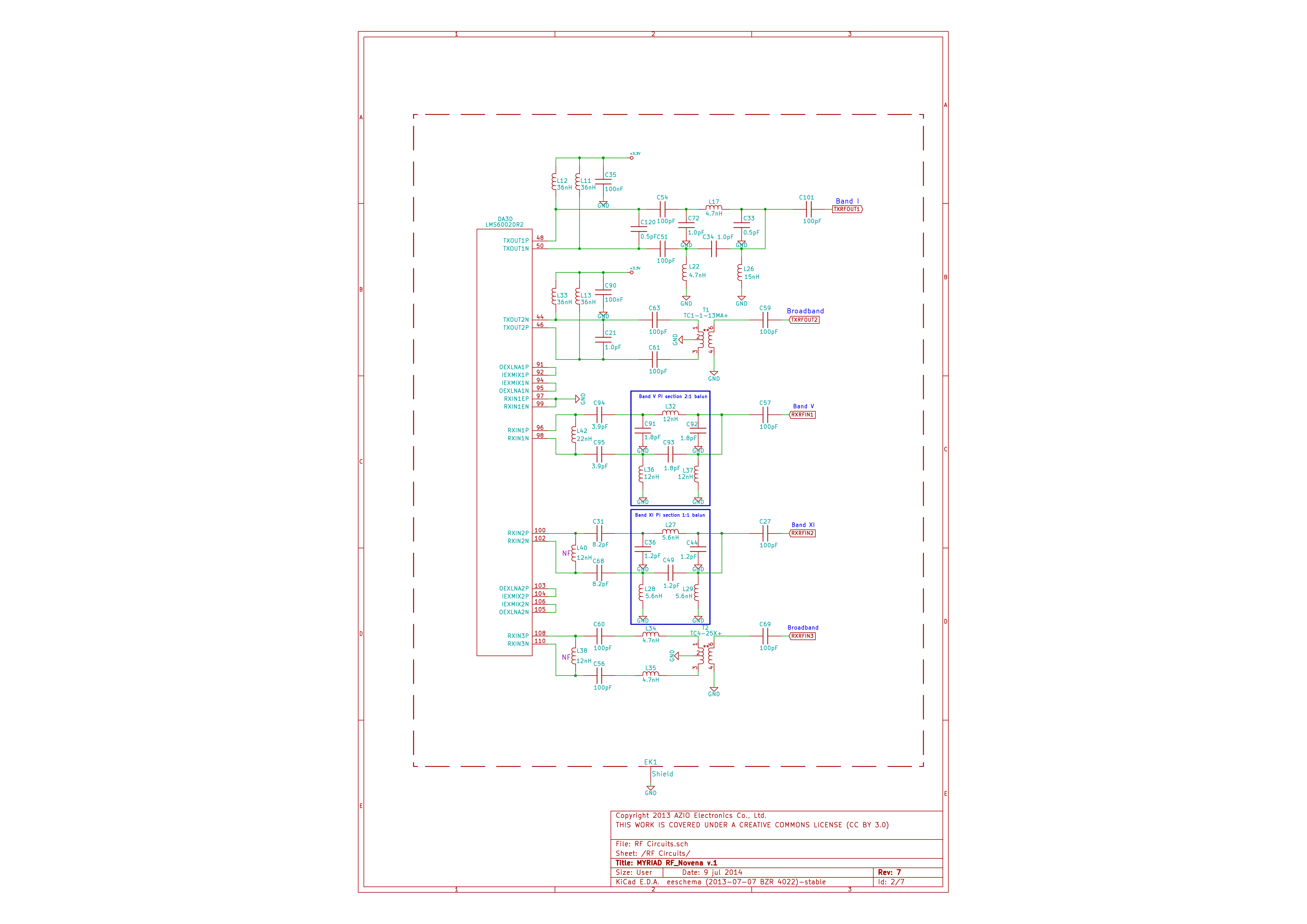
| 13:28, 22 July 2015 | Novena-RF-Schematics-1.png (file) |  |
191 KB | Novena RF Schematics Page 1, RF Circuits. | 1 |
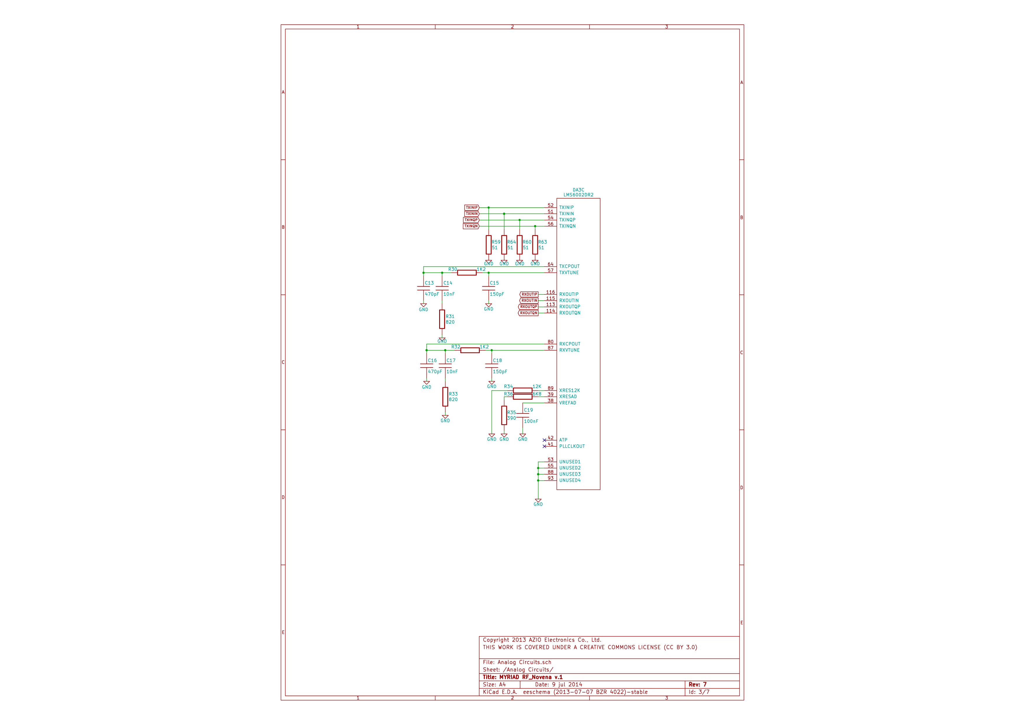
| 13:28, 22 July 2015 | Novena-RF-Schematics-2.png (file) |  |
124 KB | Novena RF Schematics Page 2, Analogue Circuits. | 1 |
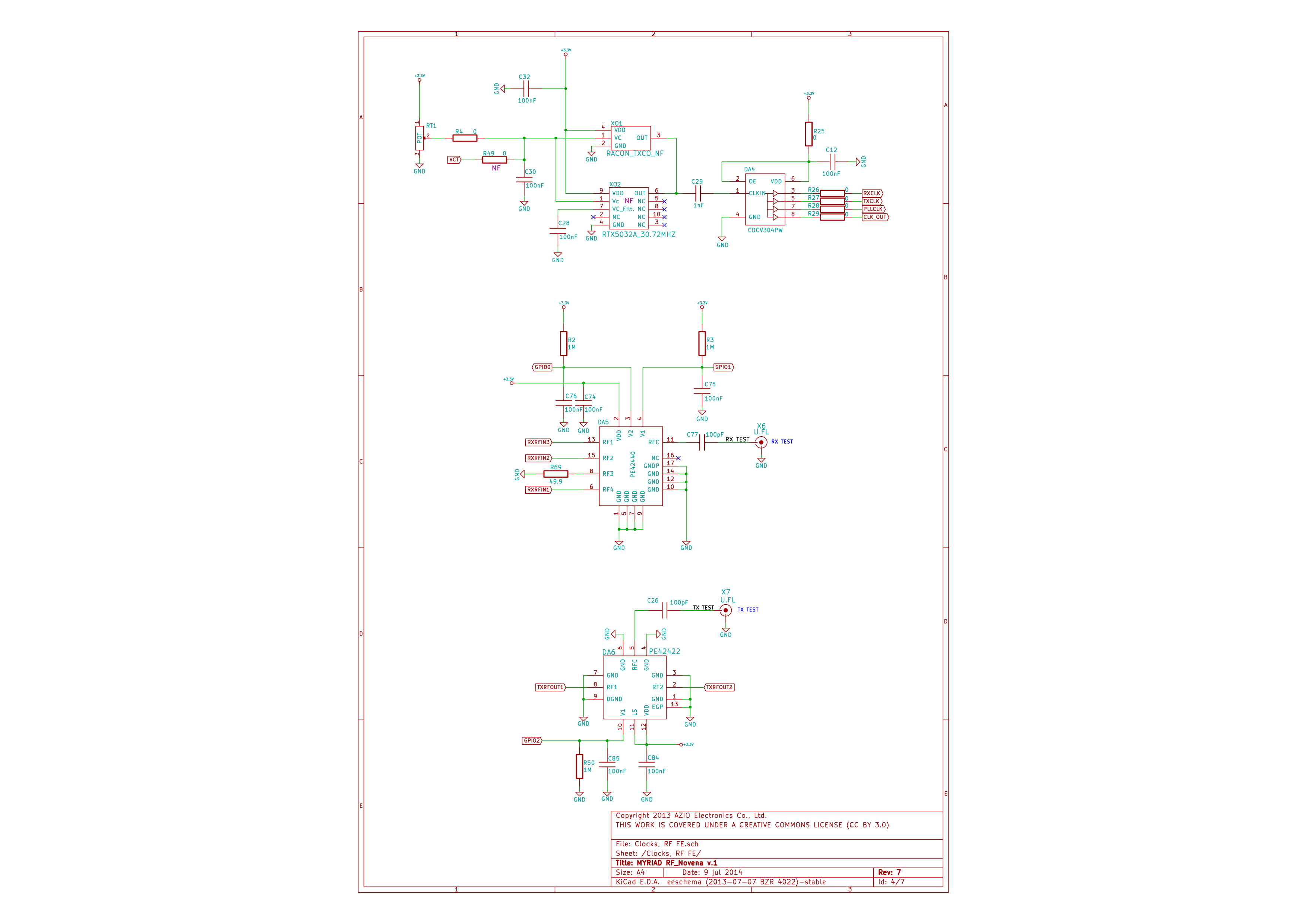
| 13:29, 22 July 2015 | Novena-RF-Schematics-3.png (file) |  |
167 KB | Novena RF Schematics Page 3, Clocks & RF FE. | 1 |
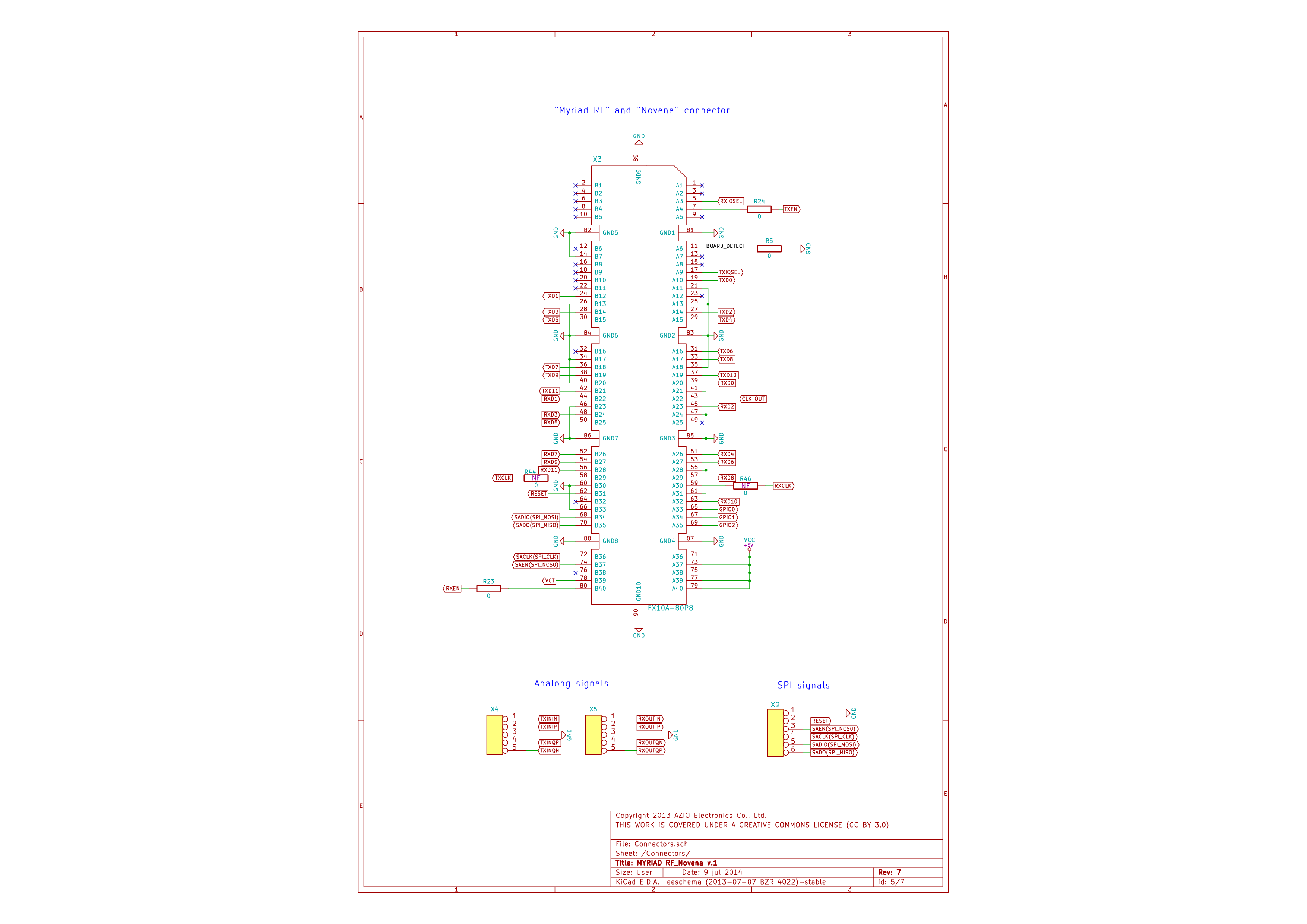
| 13:30, 22 July 2015 | Novena-RF-Schematics-4.png (file) |  |
216 KB | Novena RF Schematics Page 4, Connectors. | 1 |
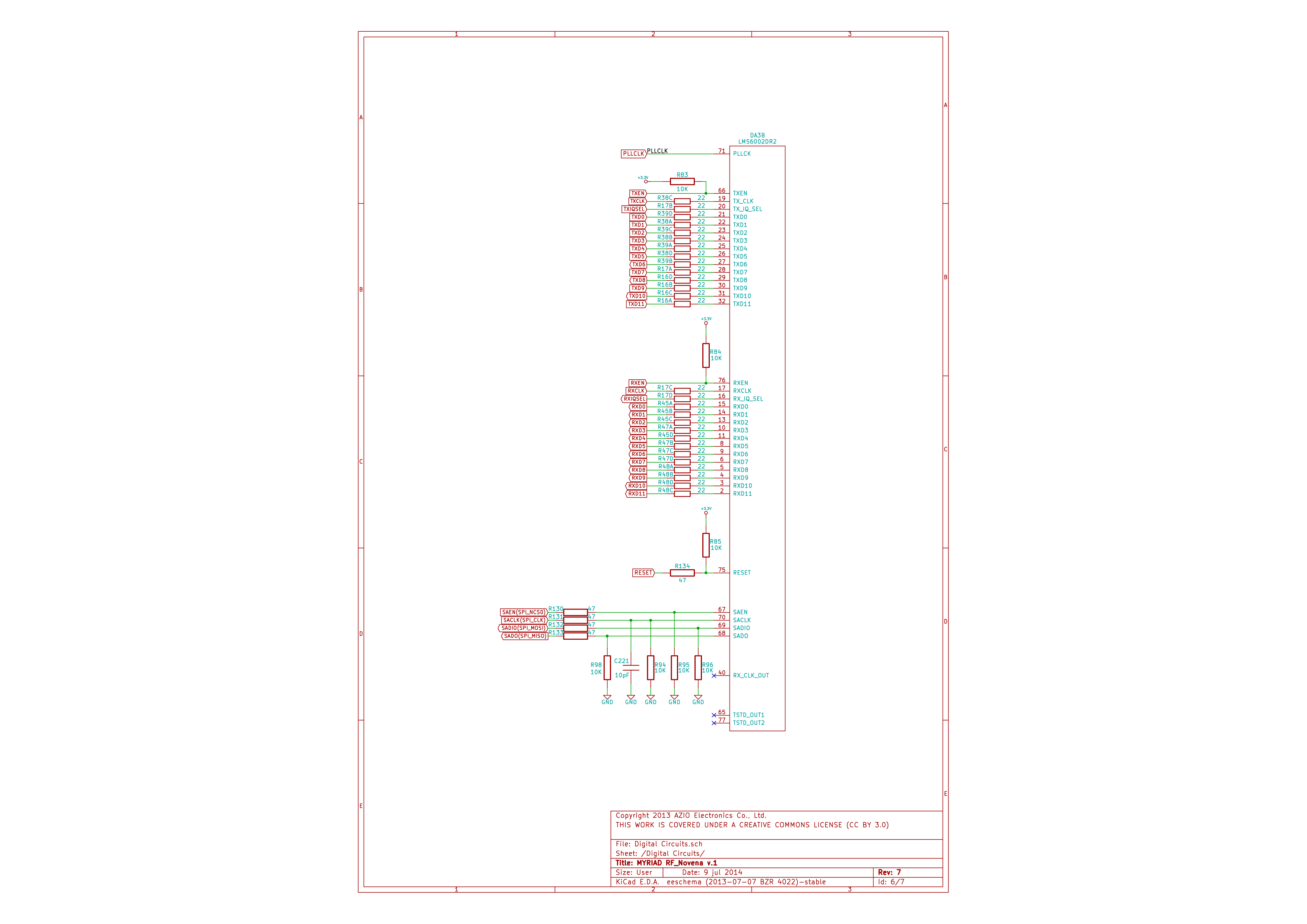
| 13:30, 22 July 2015 | Novena-RF-Schematics-5.png (file) |  |
184 KB | Novena RF Schematics Page 5, Digital Circuits. | 1 |
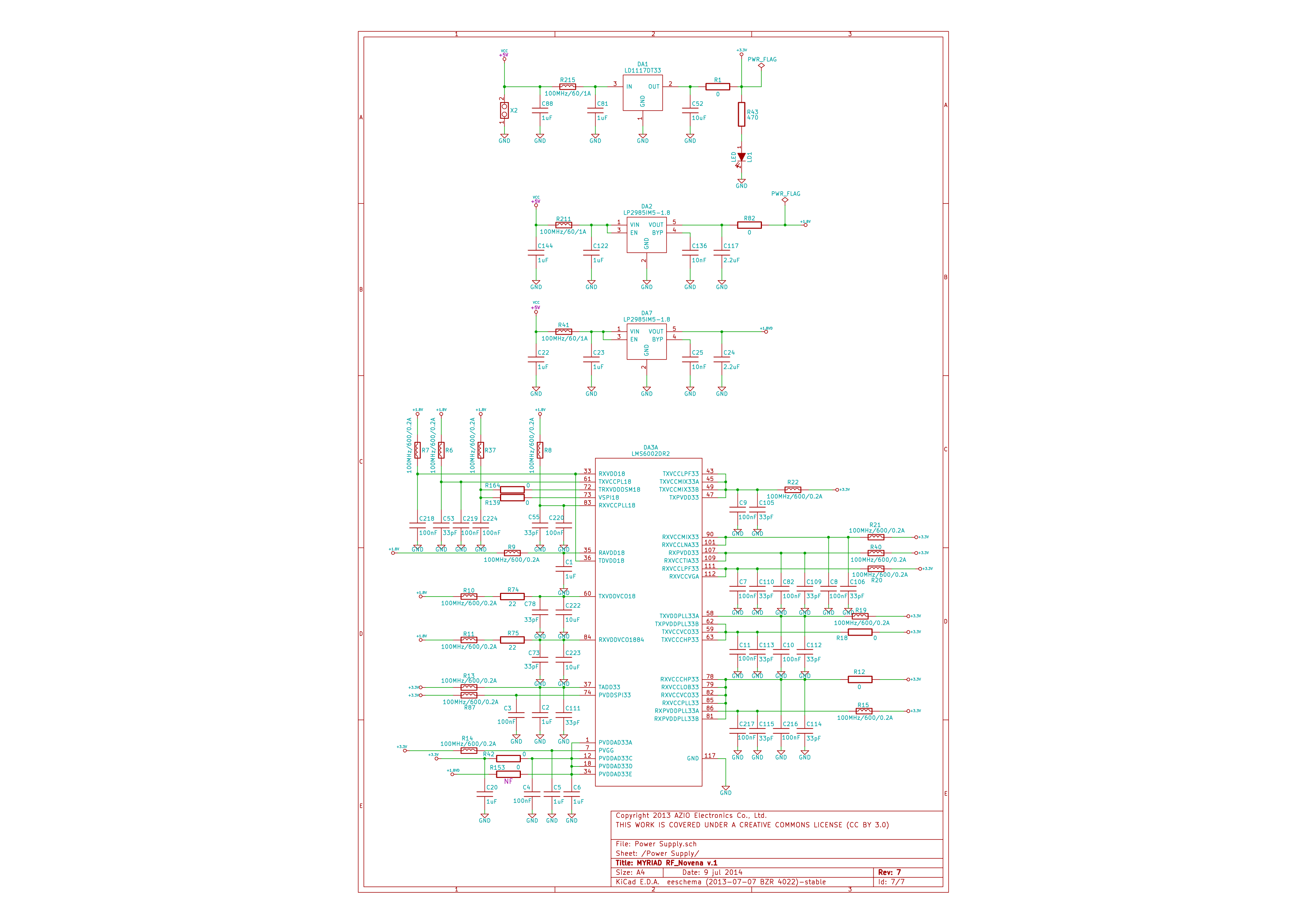
| 13:30, 22 July 2015 | Novena-RF-Schematics-6.png (file) |  |
267 KB | Novena RF Schematics Page 6, Power Supply. | 1 |