Zipper Interface Board: Difference between revisions
Ghalfacree (talk | contribs) (Initial page creation.) |
Ghalfacree (talk | contribs) (Added schematics as a gallery.) |
||
| Line 12: | Line 12: | ||
===Schematics=== | ===Schematics=== | ||
<gallery> | |||
File:Zipper-Interface-Board-Schematics-1.png|Data interface connector | |||
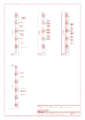
File:Zipper-Interface-Board-Schematics-2.png|HSMC & pin header connectors | |||
File:Zipper-Interface-Board-Schematics-3.png|FMC connector | |||
File:Zipper-Interface-Board-Schematics-4.png|Clock generator | |||
File:Zipper-Interface-Board-Schematics-5.png|Power supply | |||
File:Zipper-Interface-Board-Schematics-6.png|Buffers | |||
File:Zipper-Interface-Board-Schematics-7.png|Microcontroller | |||
File:Zipper-Interface-Board-Schematics-8.png|ADF4002 | |||
</gallery> | |||
===See Also=== | ===See Also=== | ||
Revision as of 14:52, 16 July 2015
About
The Zipper Interface Board is designed to allow any Field-Programmable Gate Array (FPGA) development system supporting the High-Speed Mezzanine Card (HSMC) or FPGA Mezzanine Card (FMC) standards to be connected to the Myriad-RF1 to form the Reference Development Kit. The combination of the Zipper and Myriad-RF 1 boards provides a low-cost universal radio development platform, based on the flexible, multi-standard Field Programmable Radio Frequency (FPRF) LMS6002D device. It enables developers to implement their products for a wide variety of wireless communication applications efficiently.
Images
-
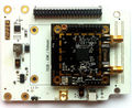
Zipper Interface Board, top
-
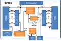
Zipper Interface Board block diagram


Connections
The Zipper Interface Board features numerous on-board connections, in addition to those available on the Myriad-RF 1 itself. A full list of available connections is available on the page Zipper Interface Board Connections.
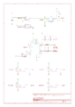
Schematics
-
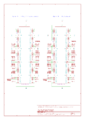
Data interface connector
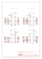
-

HSMC & pin header connectors
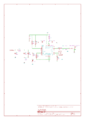
-
FMC connector
-
Clock generator
-

Power supply
-
Buffers
-

Microcontroller
-
ADF4002


